
Image coding and decoding apparatus, method of image coding and decoding, and recording medium for recording program for image coding and decoding

a technology applied in the field of image coding and decoding apparatus, method of recording medium for image coding and decoding, can solve the problems of large amount of operations, increase the cost of the apparatus, and the size of the decoding table becomes larger, so as to shorten the processing time of the image decoding

Inactive Publication Date: 2006-07-18
PANASONIC CORP
View PDF11 Cites 36 Cited by
  • Summary
  • Abstract
  • Description
  • Claims
  • Application Information

AI Technical Summary

Benefits of technology

[0044]The object of the present invention is to shorten the processing time during the image compression and image decoding, and in particular to improve the image processing time performance of an apparatus which uses a general-purpose microcomputer to process an image.
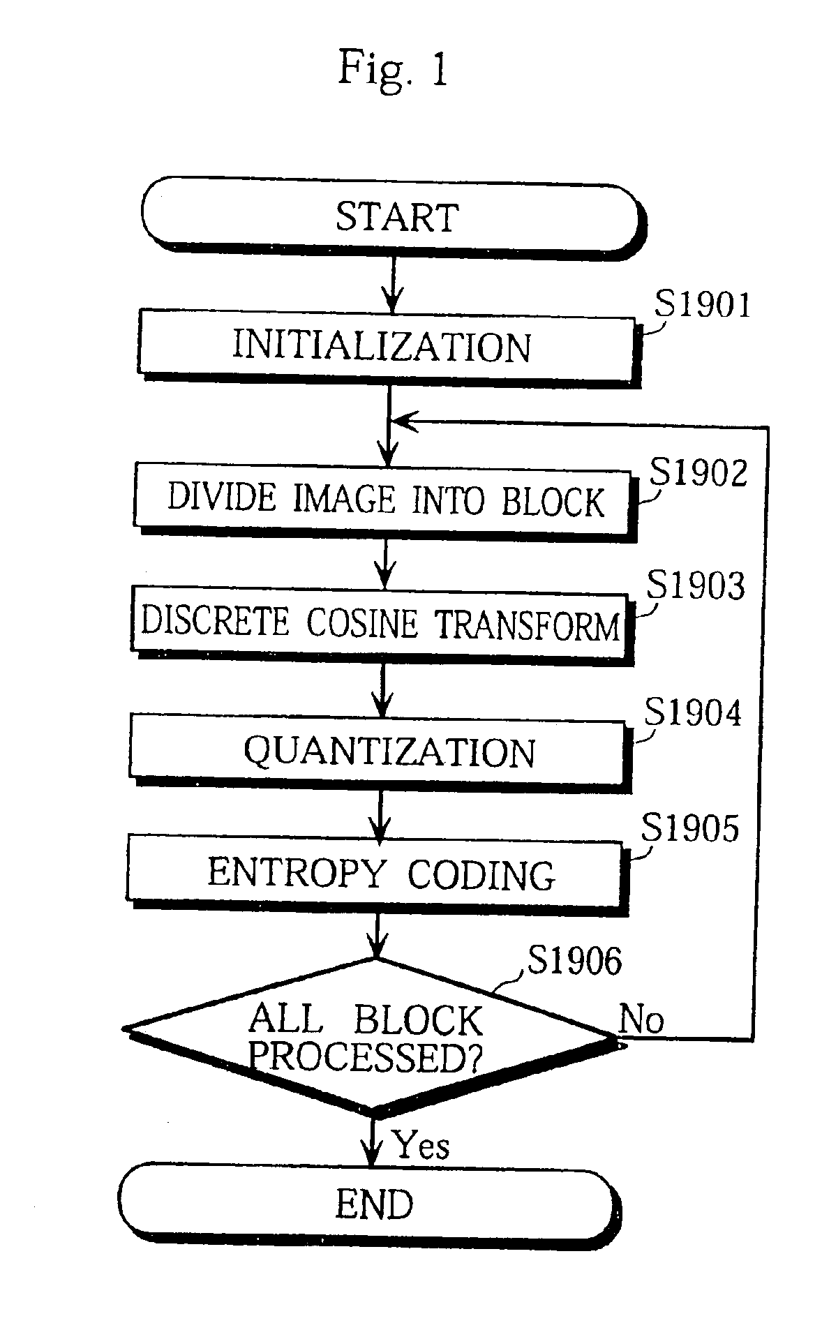
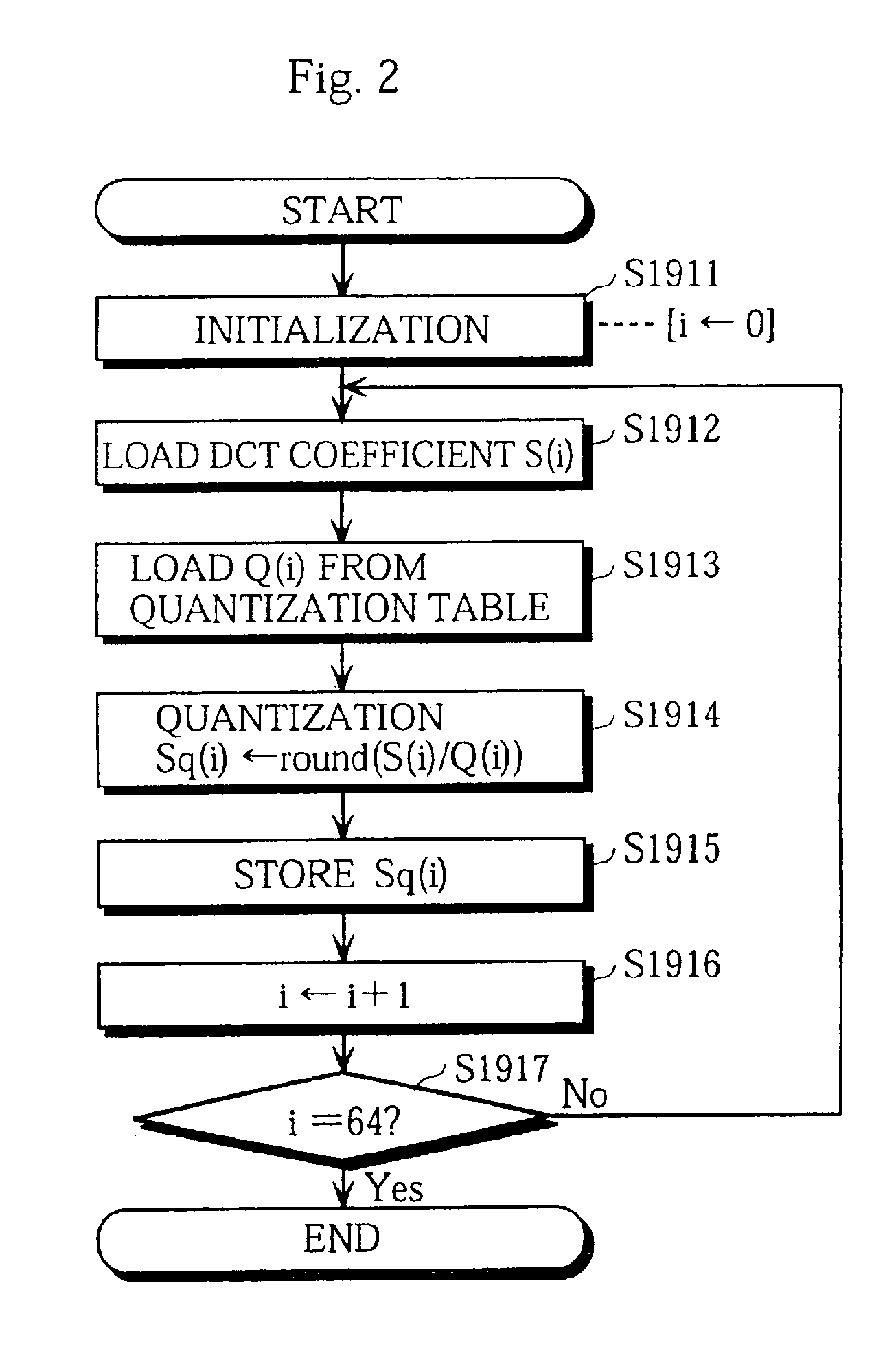
[0046]With this structure, the quantization is also performed in the entropy coding step so that the storing of quantized DCT coefficients, the loop control, and the loading of quantized DCT coefficients can be omitted, which are necessary for a conventional image coding apparatus. As a result, the processing time during the image coding is shortened.
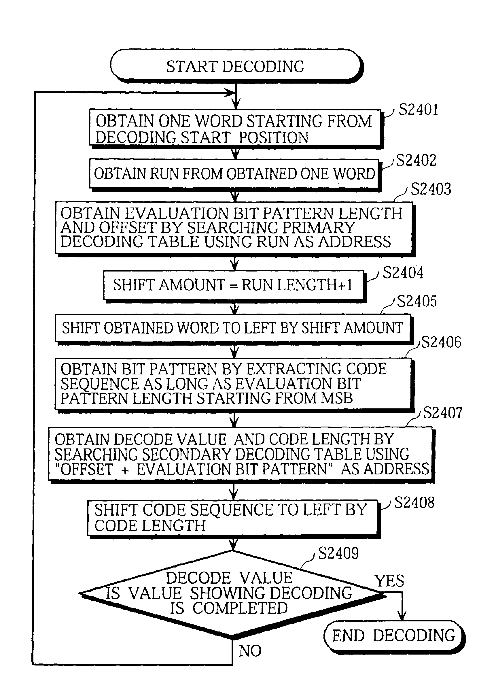
[0048]With this structure, the entropy decoding and dequantization are successively performed on each code so that the storing of quantized DCT coefficients, the loading of quantized DCT coefficients, and the loop control can be omitted, which are necessary for a conventional image coding apparatus. As a result, the processing time during the image decoding is shortened.

Problems solved by technology

However, as the longest code sequence length becomes longer, the size of the decode table becomes larger.
As a result, there is a problem that more memory capacity is required, which increases the cost of the apparatus.
However, this image processing for the image compression coding and image decoding needs a very large amount of operations, so that a general-purpose microcomputer will require a long time for this image processing.
This is because a large number of memory load and store operations need to be performed due to the very large amount of data of an image, and because many operations which require a long processing time are used in this image processing.
However, these devices are high-priced, resulting in the increased cost of products.

Method used


Image

  • Image coding and decoding apparatus, method of image coding and decoding, and recording medium for recording program for image coding and decoding
  • Image coding and decoding apparatus, method of image coding and decoding, and recording medium for recording program for image coding and decoding
  • Image coding and decoding apparatus, method of image coding and decoding, and recording medium for recording program for image coding and decoding

Examples


embodiment 1

1. Embodiment 1

[0086]FIG. 12 is a block diagram of the digital still camera of an embodiment of the present invention. The digital still camera in this figure includes: the microcomputer 1119 for controlling the camera and for performing the compression coding and the expansion decoding on images; the image photographing unit 1120 for converting images into electric signals using a CCD; the memory 1121 for temporarily storing information of photographed images to perform the compression coding and the expansion decoding on the images, the memory 1121 including a RAM used for the operation of the microcomputer 1119 and a ROM for storing a control program for controlling the microcomputer 1119; the memory card 1122 for storing data of compressed images (compression code sequence) obtained after the photographed images are subjected to the compression coding; and the liquid crystal display unit 1123 for displaying the photographed images.

1.1 Procedure for Compression Coding of Image

[00...

embodiment 2

2. Embodiment 2

[0121]The following is a description of an embodiment of the entropy decoding process of the digital still camera shown in FIG. 12, namely Steps S1141 and S1146 in the flowchart shown in FIG. 18. The entropy decoding principle of a code sequence, the structure of decodig tables, the operation of entropy decoding process, the operation of run detection, and examples of the primary decoding table and the secondary decoding table are described with reference to the drawings.

2.1 Principle of Entropy Decoding

[0122]The following is a description of the principle of the entropy decoding used for this embodiment.

[0123]As shown in FIG. 21, a plurality of variable length codes are divided into groups so that each group includes variable length codes having the same run. Each code of the variable length codes 2057, namely a group of the run length “6,” has a unique bit sequence following the run 2052 and the different sign bit 2053 of one bit length (this unique bit sequence wil...


PUM


Abstract

In an image decoding apparatus that generates a decoded image from a code sequence. The decoding apparatus has a bus, a computer and a memory, wherein the computer and the memory are connected to each other via the bus. The code sequence is generated by performing orthogonal transform, quantization and entropy coding on image data, which is stored in the memory. The decoding apparatus includes an entropy decoding unit, achieved by the computer, for reading one code out of the code sequence, which is stored in the memory, via the bus and performing entropy decoding on the read code in to generate a decode value. The apparatus also includes a coefficient generating unit, achieved by the computer, for generating at least one orthogonal transform coefficient according to the generated decode value. Also, a writing unit is achieved by the computer, for writing the generated at least one orthogonal transform coefficient into the memory via the bus. A decode controlling unit and the writing unit is provided for instructing the entropy decoding unit to process a next code out of the code sequence.

Description

[0001]The present application is a divisional application of U.S. patent application Ser. No. 10 / 041,228 filed on Jan. 7, 2002 now U.S. Pat. No. 6,643,408, which is a divisional application of U.S. patent application Ser. No. 09 / 052,468 filed on Mar. 31, 1998, now U.S. Pat. No. 6,351,570.BACKGROUND OF THE INVENTION[0002](1) Field of the Invention[0003]The present invention relates to an apparatus and a method for an orthogonal transform, a quantization, and an entropy coding of images and a medium recording a program for these coding processes, and relates to an apparatus and a method for an inverse transform and the decoding of a compressed code sequence which is obtained after the orthogonal transform, quantization, and entropy coding, and a recoding medium for recording a program for these decoding processes.[0004](2) Description of the Related Art[0005]In recent years, techniques for decoding images which have been coded and compressed with high efficiency have been extensively ...

Claims


Application Information

Patent Timeline
IPC IPC(8): G06K9/36G06K9/46G06T9/00
CPCG06T9/007
Inventor KOBAYASHI, YOSHIKAZU
Owner PANASONIC CORP
Learn More