
Method and system of determining parameters for MR data acquisition with real-time B1 optimization

a parameter and data acquisition technology, applied in the field of mr imaging, can solve the problems of subject fatigue during breath-hold applications, reduced the likelihood of subject-induced motion artifacts, and mis-registration of mr data, so as to achieve optimal peak excitation field strength, fast and simple effect, and simple

Active Publication Date: 2006-07-18
GENERAL ELECTRIC CO
View PDF7 Cites 21 Cited by
  • Summary
  • Abstract
  • Description
  • Claims
  • Application Information

AI Technical Summary

Benefits of technology

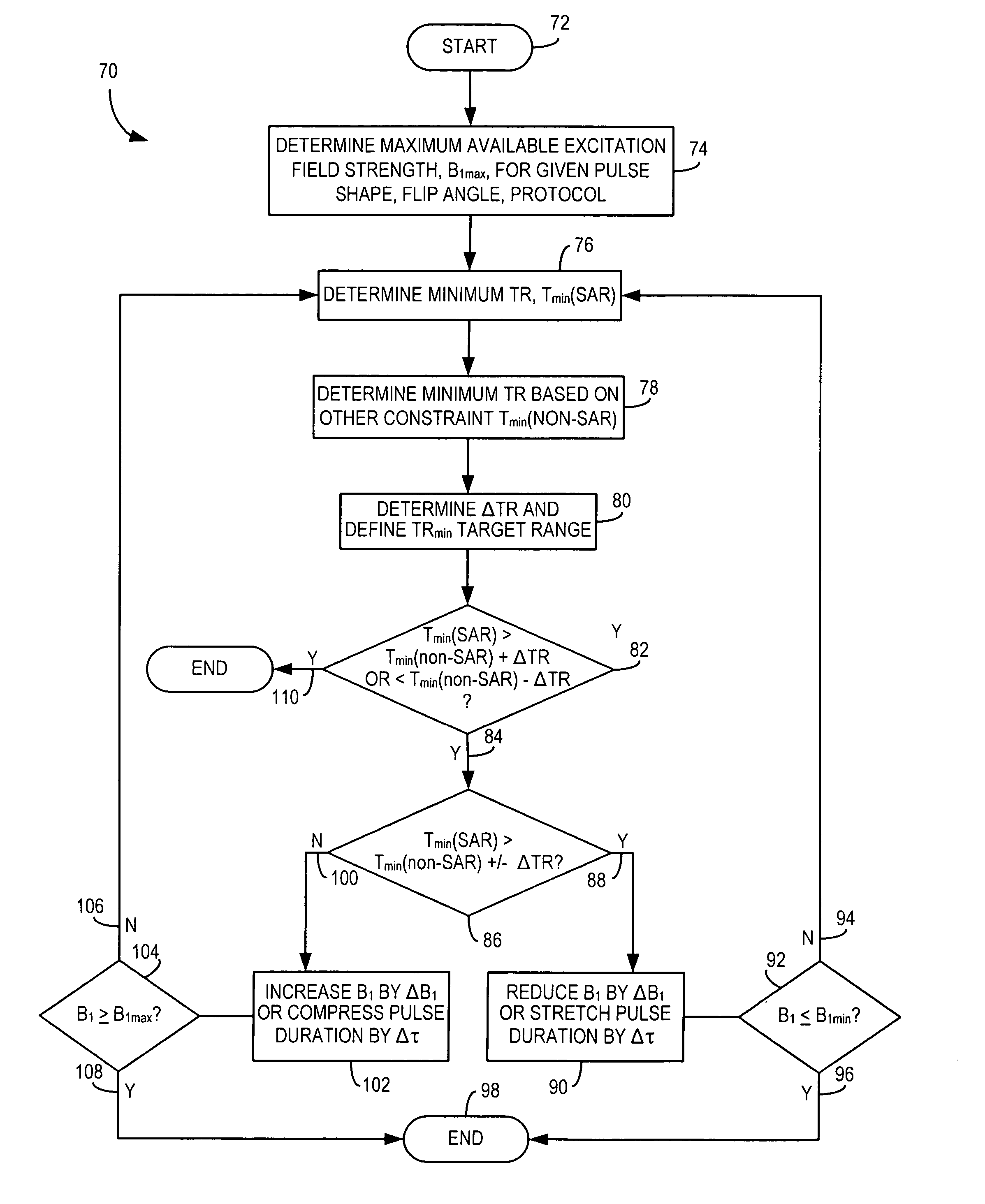
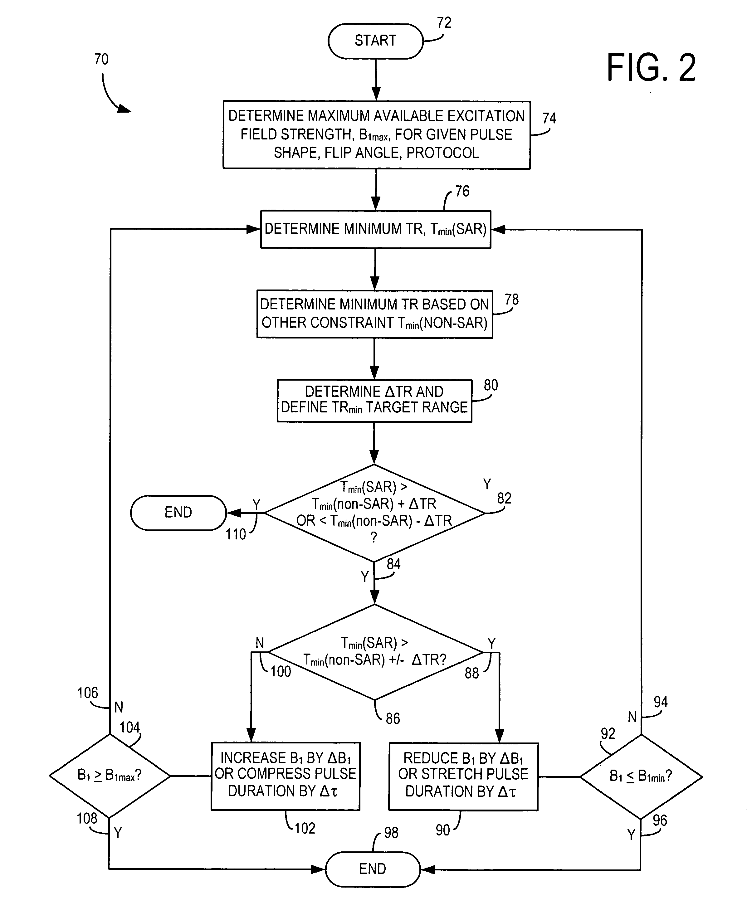
"The present invention provides a system and method for MR scan prescription that can optimize peak excitation field strength for a given pulse shape and flip angle, without being limited by SAR constraints. This allows for a faster, simpler, and more effective way to achieve the minimum TR for a pulse sequence. The invention can be used with a variety of imaging techniques and at high field strengths. The computer program can determine the minimum TR based on the excitation pulse parameters and adjust the strength of the excitation pulse accordingly. The technical effects of the invention include achieving high-resolution MR images in relatively short repetition times and overcoming the limitations of SAR and RF hardware."

Problems solved by technology

In this regard, acquiring MR data expeditiously reduces the likelihood of subject discomfort in the MR scanner, which reduces the likelihood of subject-induced motion artifacts, mis-registration of MR data, and subject fatigue during breath-hold applications, as well as increases patient throughput.
Additionally, it has been shown that for high-field applications, relying upon the maximum available excitation field strength for pulse sequences requiring short TR and large flip angles is less than optimal.
This is a result of the minimum TR being constrained by specific absorption rate (SAR) limitations.
For instance, the SAR for an MR scan conducted at 3 T is four times the SAR of an MR scan conducted at 1.5 T. As such, pulse sequences requiring large flip angles and short TRs, while possible at 1.5 T, may be unachievable at higher magnetic field strengths, such as 3 T, because the desired TR at the high field is not feasible.
However, simply reducing the flip angle of the RF pulse might not be desirable given that alteration in signal-to-noise and / or contrast-to-noise might result in less than optimal image quality.
Additionally, simply lowering the maximum available B1 strength or magnitude of the RF pulse can degrade pulse sequence performance and, hence, negatively affect image quality severely if not performed appropriately.

Method used


Image

  • Method and system of determining parameters for MR data acquisition with real-time B<sub>1 </sub>optimization
  • Method and system of determining parameters for MR data acquisition with real-time B<sub>1 </sub>optimization
  • Method and system of determining parameters for MR data acquisition with real-time B<sub>1 </sub>optimization

Examples


Embodiment Construction

[0020]Referring to FIG. 1, the major components of a preferred magnetic resonance imaging (MRI) system 10 incorporating the present invention are shown. The operation of the system is controlled from an operator console 12 which includes a keyboard or other input device 13, a control panel 14, and a display screen 16. The console 12 communicates through a link 18 with a separate computer system 20 that enables an operator to control the production and display of images on the display screen 16. The computer system 20 includes a number of modules which communicate with each other through a backplane 20a. These include an image processor module 22, a CPU module 24, and a memory module 26, known in the art as a frame buffer for storing image data arrays. The computer system 20 is linked to disk storage 28 and tape drive 30 for storage of image data and programs, and communicates with a separate system control 32 through a high speed serial link 34. The input device 13 can include a mou...


PUM


Abstract

The present invention provides a system and method of MR scan prescription to achieve in a fast, simple, and effective manner the optimal peak excitation field strength for a given pulse shape and flip angle such that the minimum TR for the MR scan can be optimized and based on SAR constraints. The present invention provides a technique to obtain optimal B1 parameters for an arbitrary shape and flip angle of an excitation pulse in real-time while satisfying SAR and / or RF hardware limits to determine the minimum achievable repetition time for a pulse sequence. The present invention is particularly applicable with breath-hold and cardiac imaging techniques that are carried out at relatively high field strengths.

Description

BACKGROUND OF THE INVENTION[0001]The present invention relates generally to MR imaging and, more particularly, to a method and system of determining and setting excitation pulse parameters for MR data acquisition to minimize repetition time for a given pulse sequence without exceeding prescribed electromagnetic energy exposure levels and RF heating limits.[0002]When a substance such as human tissue is subjected to a uniform magnetic field (polarizing field B0), the individual magnetic moments of the spins in the tissue attempt to align with this polarizing field, but precess about it in random order at their characteristic Larmor frequency. If the substance, or tissue, is subjected to a magnetic field (excitation field B1) which is in the x-y plane and which is near the Larmor frequency, the net aligned moment, or “longitudinal magnetization”, MZ, may be rotated, or “tipped”, into the x-y plane to produce a net transverse magnetic moment Mt. A signal is emitted by the excited spins ...

Claims


Application Information

Patent Timeline
Patent Type & Authority Patents(United States)
IPC IPC(8): G01V3/00
CPCG01R33/288G01R33/5659G01R33/583
Inventor VU, ANTHONY T.
Owner GENERAL ELECTRIC CO
Learn More