
Injection molding of lens

a technology of injection molding and lens, which is applied in the field of injection molding of lens, can solve the problems of unsatisfactory solutions, inability to achieve the effect of stable photochromic effect, good photochromic efficiency and durability, and simple and efficient

Inactive Publication Date: 2006-07-18
HOYA OPTICAL LABS OF AMERICA INC
View PDF30 Cites 55 Cited by
  • Summary
  • Abstract
  • Description
  • Claims
  • Application Information

AI Technical Summary

Benefits of technology

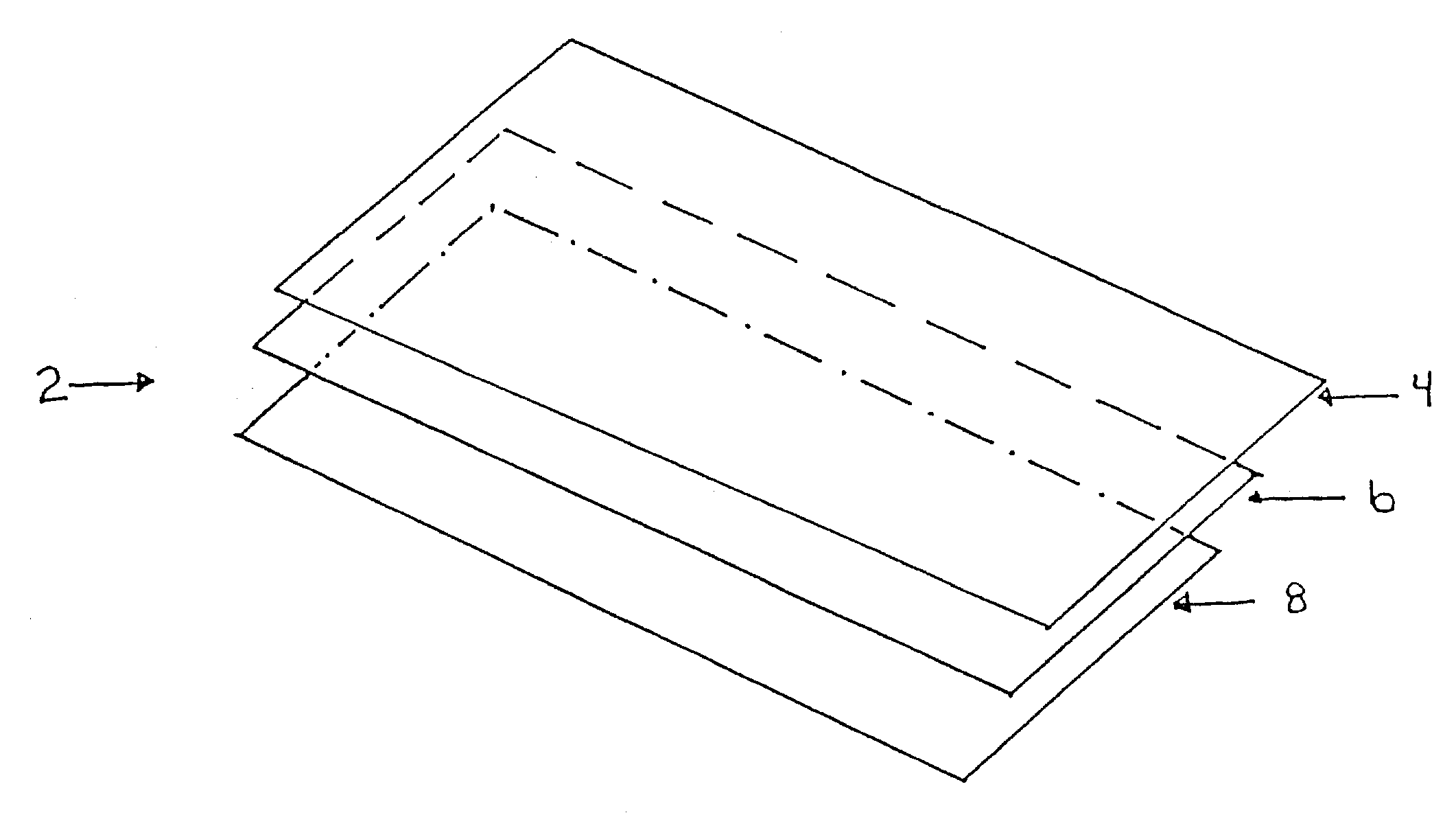
The patent describes a way to create a photochromic lens by using a special layered structure that can be applied to a lens blank or a ground lens. This layered structure includes a thin layer of a light-transmissive polymer, a photochromic layer, and a thicker layer of a light-transmissive polymer. This lens blank can then be further shaped and ground to create the desired optical properties. The use of this special layered structure allows for precise control over the photochromic effect and durability, and can be applied to a variety of lens materials. The resulting lens has good optical properties and is suitable for use in photochromic optical lens production.

Problems solved by technology

The introduction of a photochromatic compound into the mass of an article, especially when this is made of thermoplastic material, can, on the other hand, create problems to which no satisfactory solution has yet been found.
In the conditions, especially of temperature, under which these processes are carried out, the organic photochromatic compounds are likely to undergo degradation or at least degeneration, accompanied by the irreversible development of undesirable coloring.
In addition, it is also known that organic photochromatic compounds incorporated in polymer matrices or in solutions, undergo rapid degradation, losing their photochromatic activity due to exposure to light under normal conditions of use.
It will be appreciated that production of a composite lens blank by a process which requires that separate inner and outer lens elements be first ground and polished and, then, bonded (laminated) together with a preformed (curved) photochromic layer there between will be a tedious, labor-intensive and inefficient process.
Similarly, production of a lens blank by resort to a method which requires the preforming of a curved photochromic layer, placement of the preformed photochromic element into a mold, filling of the mold with polymerizable monomer, curing (polymerization) of the monomer and release of the curved blank or lens from the mold will be labor intensive, time-consuming and inefficient.
Glass is not, however, adapted readily to convenient forming (e.g., thermoforming or bending) methods.
Moreover, depending upon the particular materials used, the forming method may induce strain and orientation in the photochromic layer or the lighttransmissive layers of the lens blank, manifested by optical distortion and reduced consistency or efficiency of the photochromic layer.
Sufficient distortion of the photochromic layer can cause streaking visible both to the wearer and to an observer of the lenses.
Depending upon the nature of polymerizable monomer used in a method based upon in situ polymerization in a mold, shrinkage of the cured resin and the development of physical strains can result in reduced consistency or efficiency.

Method used


Image

  • Injection molding of lens
  • Injection molding of lens

Examples


examples

[0071]To obtain meaningful numbers for data on the performance of photochromic laminates on polycarbonate surfaces, a controlled experiment was done to measure the amounts of degradation obtained after an accelerated fatigue test on samples placed in a xenon lamp fadometer. The urethane polymers selected for comparison were both polyester urethanes (e.g., polyesters derived from polyester polyols or diols), herein called resin “A” (CLC-93A, Thermedics Corp, Woburn, Mass.), and polyether urethanes (derived from polyether polyols or diols), herein called resin “B” (PT-7500, Deerfield Urethane, Deerfield, Mass.).

[0072]Two test formulations were prepared, one with each of the two polymer types, resin A and resin B, Polyester and Polyether, respectively. Both formulations had the same weight proportions of the combination of ingredients consisting of CR49 0.66%, CR59 0.10%, Uvinul® 3040 0.30%, Tinuvin® 144 2.00%, Tinuvin.F 765 2.00%, the urethane solids comprised the remainder up to 100%...


PUM

PropertyMeasurementUnit
thicknessesaaaaaaaaaa
thicknessaaaaaaaaaa

Abstract

A flat or curved photochromic laminate structure and a plastic photochromic lens blank can be produced in a simple and efficient manner from relatively low-cost polymeric sheet materials. These laminates can be used to provide goggles, face shields, windows, window coverings, skylights, and optical lenses having efficient, uniform and high quality photochromic properties. The use of a polyesterurethane as the binder for the photochromic material has been found to improve the performance of the photochromic material. There may be a desire to have a protective exterior layer (e.g., an abrasion resistant layer) in combination with the lens system, but that may be provided in various methods. In the case of using the laminate in a goggle application, the laminate may be hard coated on one or both outer surfaces with an abrasion resistant coating, antireflective coating, and / or an anti-fog hard coating.

Description

CROSS REFERENCE TO RELATED APPLICATIONS[0001]This application is a provisional application of U.S. Application Ser. No. 60 / 364,839 filed Mar. 13, 2002 entitled INJECTION MOLDING OF OPHTHALMIC LENS. It is a continuation-in-part application of U.S. application Ser. No. 09 / 854,419 filed May 11, 2001 entitled PROVISION OF PHOTOCHROMIC LAYERS ON POLYMERIC SURFACES, now abandoned. It is also a continuation-in-part application of U.S. application Ser. No. 09 / 580,162 filed May 30, 2000 entitled MANUFACTURING OF POSITIVE POWER OPHTHALMIC LENSES, now U.S. Pat. No. 6,390,621. Each of these documents are included by reference in this application in their entirety.BACKGROUND OF THE INVENTION[0002]This invention relates to formulation of laminate functional layers both in their use alone or in the injection molding of ophthalmic lenses. It also relates to injection molding of ophthalmic lenses. In this regard, the following patent documents are hereby incorporated by reference into this applicati...

Claims


Application Information

Patent Timeline
Patent Type & Authority Patents(United States)
IPC IPC(8): B29D11/00B29C45/14B29C45/73G02B5/23
CPCB29C45/73B29D11/00028B29D11/00432B29D11/0073B32B27/36G02B5/23G02B5/3033G02C7/102B29C45/14811B29C45/1418G02C2202/16B29K2069/00B29K2075/00B29K2081/06B29K2995/0018B29L2011/0016Y10T428/31551
Inventor MAKI, ALAN D.WOELFLE, ERIC J.KROULIK, DARRELL B.MORAVEC, THOMAS J.TRAVNICEK, EDWARD A.HAGE, MARTIN L.
Owner HOYA OPTICAL LABS OF AMERICA INC
Learn More