
Disc drive and recording-disc loading control method

a technology of recording discs and control methods, applied in the direction of digital signal error detection/correction, instruments, recording signal processing, etc., can solve the problems of long loading time, delayed response to the host cb>10, and longer time necessary for loading, so as to reduce the response time to the host and high probability. , the effect of shortening the time necessary for loading

Inactive Publication Date: 2006-07-11
FUJITSU LTD
View PDF9 Cites 3 Cited by
  • Summary
  • Abstract
  • Description
  • Claims
  • Application Information

AI Technical Summary

Benefits of technology

[0020]It is therefore an object of the present invention, as mentioned at the beginning, to reduce the loading time of the recording disc. More comprehensively and specifically, an object of the present invention is to provide a disc drive and a control method therefor for loading the recording disc, capable of reducing the response time when data reading and / or writing is performed before and after the same disc is ejected and then inserted again.
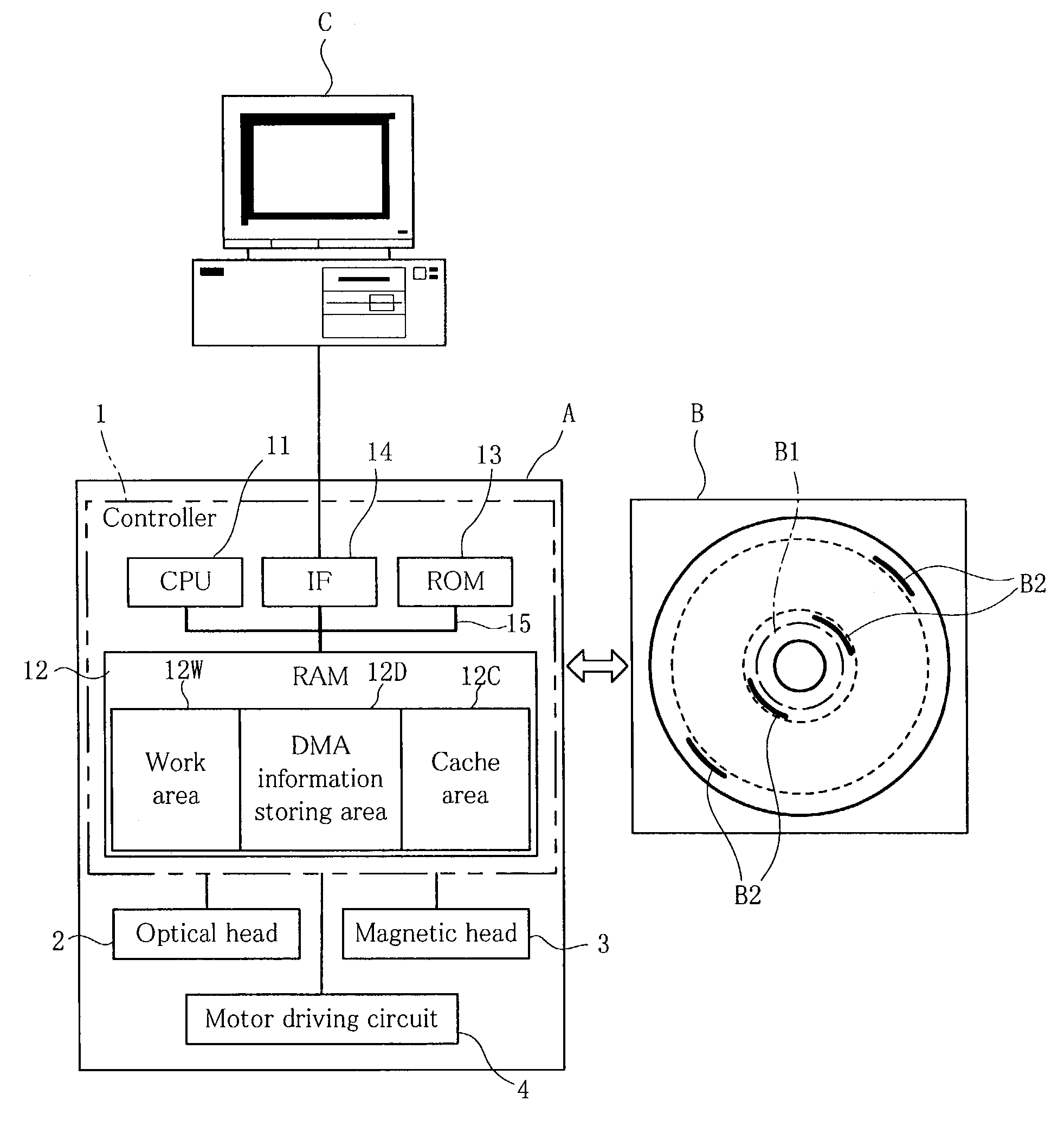
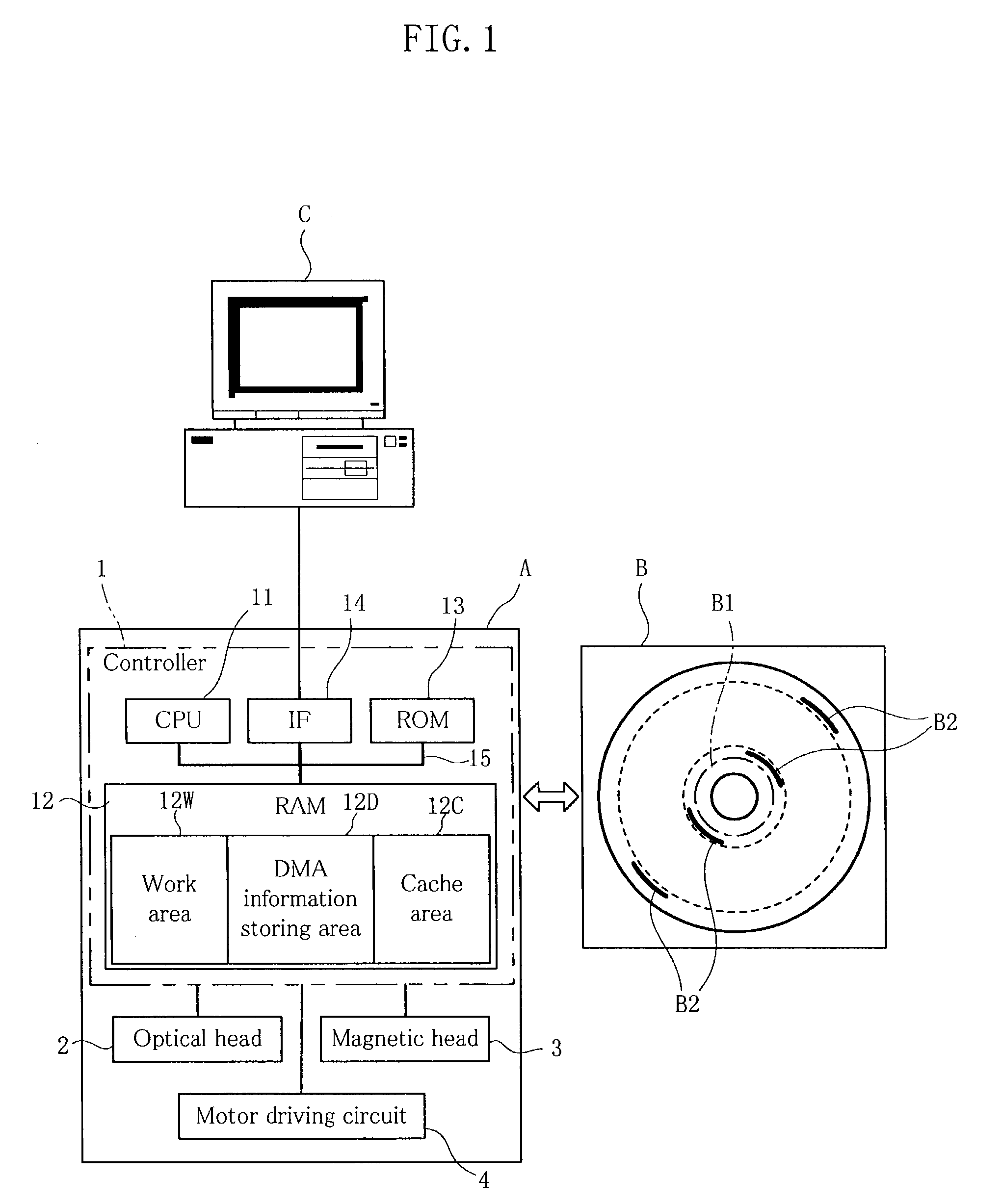
[0031]Therefore, when a recording disc is ejected and then re-inserted for reading / writing of data, the step of reading DMA information is not performed in the second loading, and the time necessary for the loading is shorter accordingly than in the first time. Therefore, when a command is issued for reading / writing of data upon the second loading, it is possible to reduce response time to the host in data transfer. Likewise, when the same recording disc is ejected and then re-inserted for reading / writing of data, it is possible to use previous data remaining in the cache area even after the second loading. Therefore, when data is to be read upon the second loading of the second recording disc, the data can be hit in the cache area at a high probability, making possible to reduce response time accordingly.

Problems solved by technology

A result is a tendency of prolonged time for loading (a set of procedures which immediately follow disc insertion).
The capacity of magneto-optical disc will be increased further in the future, which could lead to a longer loading time.
Thus, the CPU 110 must withstand the commanded accessing operation until the loading is over, resulting in a problem of delayed response to the host C10.
So, again, there is a problem of delayed response to the host C10.

Method used


Image

  • Disc drive and recording-disc loading control method
  • Disc drive and recording-disc loading control method
  • Disc drive and recording-disc loading control method

Examples


first embodiment

[0045]As shown in FIG. 1, the present invention uses a disc drive A capable of performing a loading operation, a magneto-optical disc B as a recording disc, and a personal computer C as a host which directs reading and writing of data. The personal computer C, operating conventionally on the basis of an OS (Operating System) which provides file managing capabilities, does not have any new essential characteristics, and therefore will not be described or illustrated in specific detail.

[0046]First, the magneto-optical disc B, which is the object to be loaded, will be described. The magneto-optical disc B can be provided by MO discs, of different capacities such as 230 MB, 540 MB, 640 MB, and 1.3 GB. The magneto-optical disc B includes a multiple of tracks (not illustrated) serving as a recording area B3 for storing data. Conceptually, the magneto-optical disc B has a number of sectors each made up of a fragmented division of the tracks. Generally, in a 640 MB magneto-optical disc for ...

second embodiment

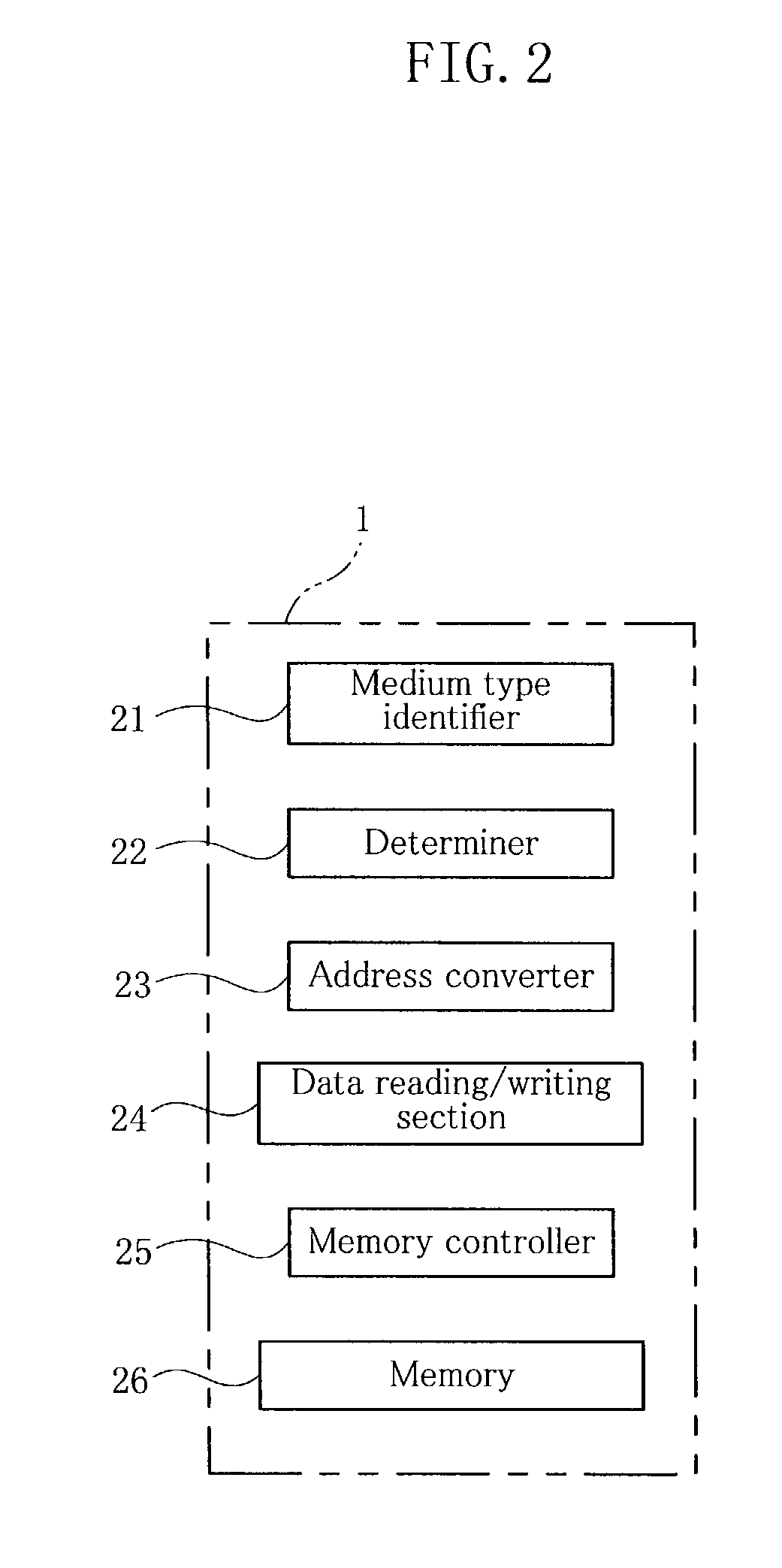
[0083]As shown in FIG. 5, the controller 1 includes a medium type identifier 31, a timer 32, a determiner 33, an address converter 34, a data reading / writing section 35, a memory controller 36, and a memory 37. Specifically, the CPU 11 provides the medium type identifier 31, the timer 32, the determiner 33, the address converter 34, the data reading / writing section 35, and the memory controller 36. The RAM 12 provides the memory 37.

[0084]The medium type identifier 31, the address converter 34 and the data reading / writing section 35 have the same function as those described in the first embodiment.

[0085]The timer 32 measures a disc changing time from ejection of a magneto-optical disc B to the next insertion of a magneto-optical disc B.

[0086]The determiner 33 is called up at the time of loading a magneto-optical disc B, and checks if the disc changing time measured by the timer 32 is longer than a predetermined norm time. The norm time is a time too short to change an ejected magnet...


PUM


Abstract

A disc drive (A) for data transfer between a magneto-optical disc (B) and a host (C) is provided. The disc drive reads and stores in a RAM (12) medium identification information unique to the magneto-optical disc (B) and DMA information (B2) including a list of addresses indicating defective areas upon loading, and performs address conversion with reference to the DMA information (B2) for the data transfer. A CPU (11) checks if the medium identification information obtained when loading the magneto-optical disc (B) is identical with or different from medium identification information obtained in the previous loading. The CPU (11) allows the reading of DMA information (B2) and replacing of the previous DMA information remaining in a DMA information storage area (12D) of the RAM (12) with the newly obtained DMA information only when the newly obtained medium identification information is different from the previous medium identification information.

Description

REFERENCE TO RELATED APPLICATION[0001]This application is a continuation of International Application PCT / JP00 / 04916 filed Jul. 21, 2000.TECHNICAL FIELD[0002]The present invention relates to a disc drive which is loaded with a removable recording disc such as a magneto-optical disc, and to a control method therefor for loading the recording disc.BACKGROUND ART[0003]Recent magneto-optical discs have increasingly large capacities, and accordingly can allow an increasing number of defective sectors to be therein. This means increase in the volume of information contained in DMA (Defect Management Area) which is an address list of defective sectors in the magneto-optical disc. A result is a tendency of prolonged time for loading (a set of procedures which immediately follow disc insertion). For example, a magneto-optical disc having a capacity of 1.3 GB needs a loading time of about twelve seconds. The capacity of magneto-optical disc will be increased further in the future, which could...

Claims


Application Information

Patent Timeline
IPC IPC(8): G06F11/00G11B20/10G11B20/12G11B20/18
CPCG11B20/10G11B20/1217G11B20/1883G11B2220/2525G11B2220/20
Inventor OZAKI, KOJI
Owner FUJITSU LTD
Learn More