
Microwave resonator and filter assembly

a technology of resonator and filter assembly, which is applied in the direction of waveguide type devices, resonators, basic electric elements, etc., can solve the problems of insufficient spurious performance, small tuning range, and various practical and operational limitations of conventional resonator structures currently being used in microwave filters, and achieve the effect of small diameter to length ratio

Inactive Publication Date: 2006-07-11
HONEYWELL LIMITED HONEYWELL LIMITÉE
View PDF16 Cites 15 Cited by
  • Summary
  • Abstract
  • Description
  • Claims
  • Application Information

AI Technical Summary

Benefits of technology

"The invention provides a resonator assembly and a resonator filter for filtering electromagnetic waves. The resonator assembly includes a resonator cavity, an elongated cylindrical dielectric resonator, and insulative supports. The resonator filter includes multiple resonator assemblies with a common cavity wall and two iris openings. The technical effects of the invention include the ability to resonate at a desired frequency and filter electromagnetic waves with high efficiency."

Problems solved by technology

Conventional resonator structures currently being used in microwave filters suffer from various practical and operational limitations including small tuning range, inadequate spurious performance, high complexity and excessive mass.
These characteristics are not optimum for use in the field of space communication applications such as satellite communications where mass, volume and electrical performance are of critical importance.
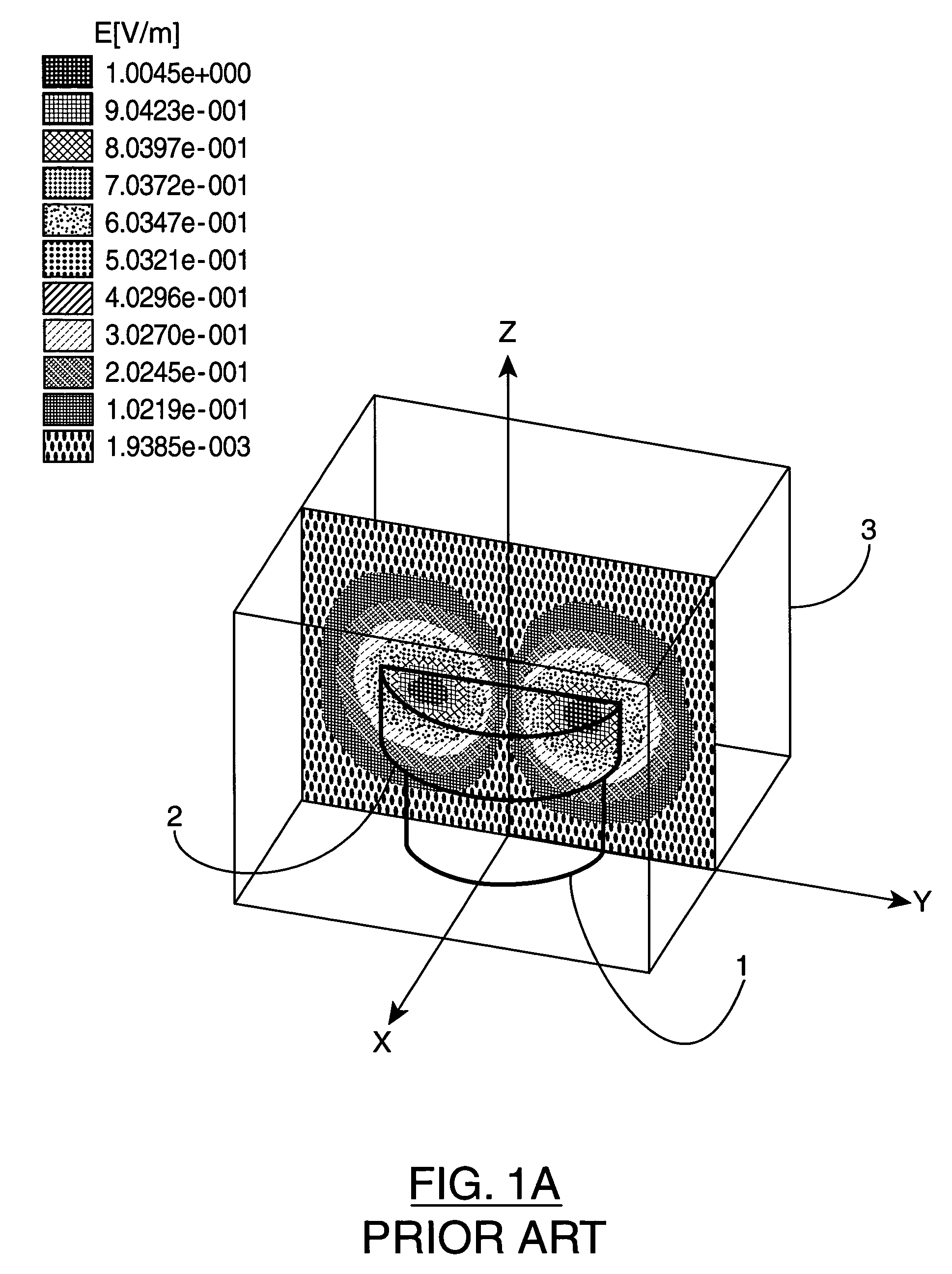
Another important disadvantage of puck resonator 2 is that since the electrical field is spread out (as shown in FIG. 1A), tuning screws do not effectively interrupt the electrical field resulting in a small tuning range.
Further, when multiple resonators are combined to form a filter, undesired (stray) couplings are generated between non-adjacent resonators and require additional diagonal probes for cancellation purposes.
These diagonal probes result in added complexity, increased mass and performance degradation for the resonator and filter assembly.
This lower Q makes the metal combline unusable for satellite multiplexer filters.
This is primarily due to the fact that the quality factor (Q) of QWD resonator 8 is limited due to losses caused by the resonator 8 and cavity 9 being in electrical contact.

Method used


Image

  • Microwave resonator and filter assembly
  • Microwave resonator and filter assembly
  • Microwave resonator and filter assembly

Examples


Embodiment Construction

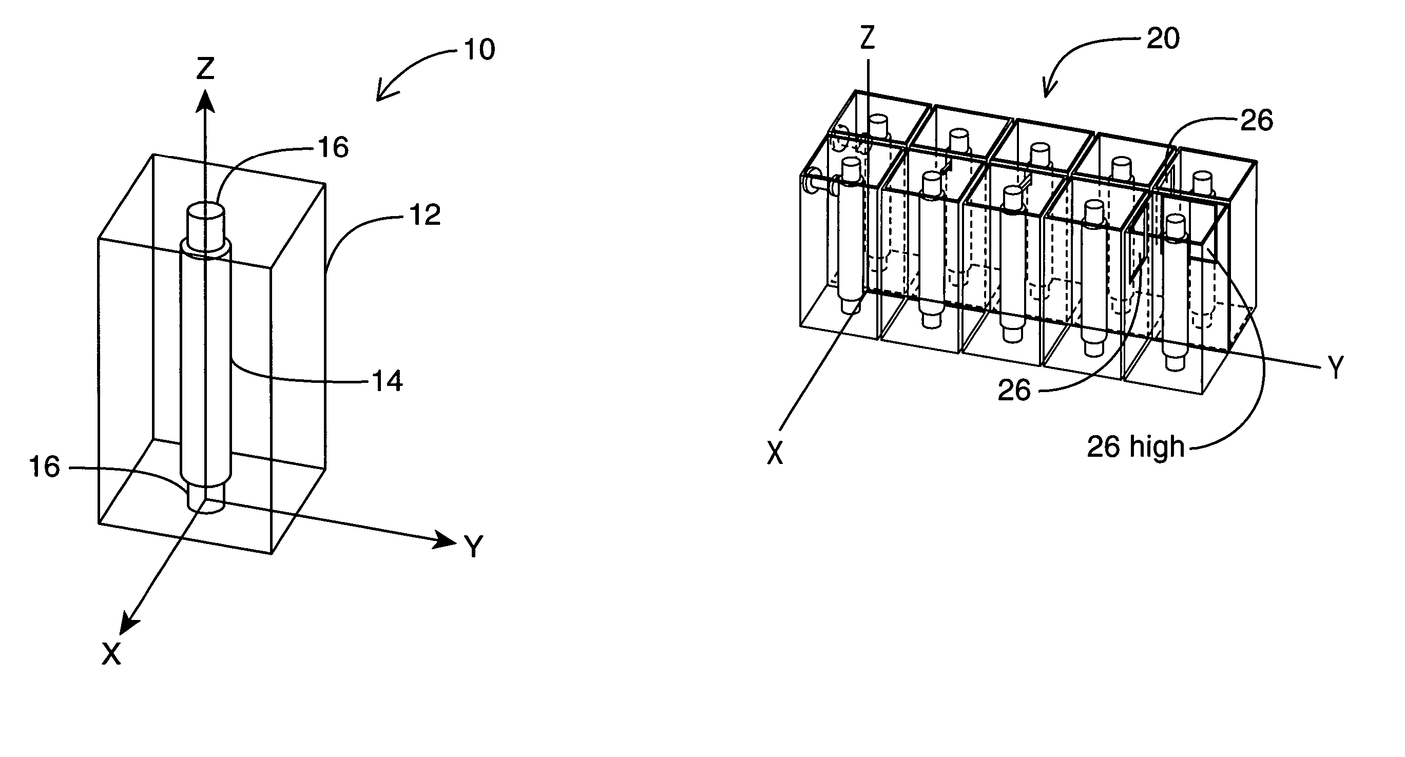
[0036]FIGS. 2A and 2B illustrate a preferred embodiment of a half wave resonator assembly 10, built in accordance with the present invention. Resonator assembly 10 operates in the TM mode, exhibits a high quality factor (Q) value and good spurious performance as will be described. Further, when a number of resonator assemblies 10 are combined into a resonator filter as will be discussed, it is possible to cancel out stray couplings without the need to use diagonal probes as will be described. Resonator assembly 10 consists of a resonator cavity 12, a cylindrical dielectric resonator 14 and end supports 16 where the dielectric resonator 14 and end supports 16 are mounted within the metallic cavity 12.

[0037]Resonator cavity 12 is a conventional resonator cavity preferably constructed of silver-plated aluminum, although many other types of materials could be used (e.g. copper, brass, etc.) As shown, resonator cavity 12 has a larger cavity height than that associated with conventional T...


PUM


Abstract

A half wave dielectric resonator assembly including a resonator cavity having a top surface and a bottom surface, an elongated cylindrical dielectric resonator positioned within said resonator cavity and first and second insulative supports to couple and insulate the ends of the cylindrical dielectric resonator from the resonator cavity. The dielectric resonator has a substantially small diameter to length ratio. The resonator assembly provides improved spurious performance and quality factor (Q) at a lower mass. A resonator filter is constructed using a plurality of these resonator assemblies, where adjacent pairs of said resonator cavities are separated from each other by a common cavity wall. By forming a first iris opening formed within a first common cavity wall and forming a second iris opening formed within a second common cavity wall having a position that is vertically offset from the position of the first iris, it is possible to reduce stray coupling.

Description

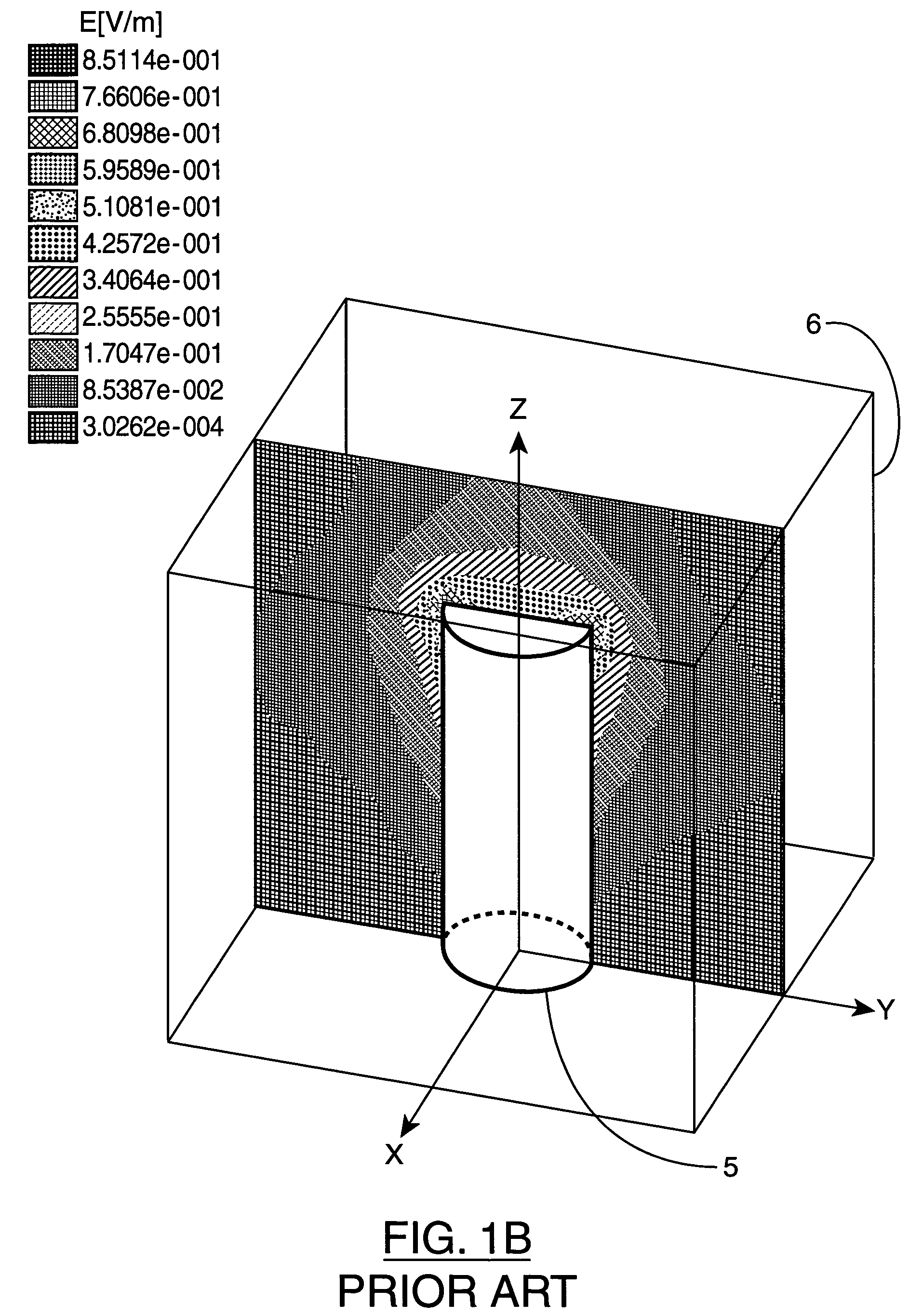
FIELD OF THE INVENTION[0001]This invention relates to microwave communication equipment and more particularly to microwave resonator and resonator filter assemblies.BACKGROUND OF THE INVENTION[0002]Conventional resonator structures currently being used in microwave filters suffer from various practical and operational limitations including small tuning range, inadequate spurious performance, high complexity and excessive mass. These characteristics are not optimum for use in the field of space communication applications such as satellite communications where mass, volume and electrical performance are of critical importance. The most commonly used prior art resonator structures for microwave filters are shown inFIGS. 1A, 1B and 1C as discussed below. The relative electric field strength is indicated by in the graphs by shading type.[0003]FIG. 1A illustrates the electrical field pattern of a conventional TE01δ mode (puck) resonator 2 that is supported by a platform support 1. Resonat...

Claims


Application Information

Patent Timeline
Patent Type & Authority Patents(United States)
IPC IPC(8): H01P7/10H01P1/201
CPCH01P7/10
Inventor SMITH, DAVID JOHNYU, MING
Owner HONEYWELL LIMITED HONEYWELL LIMITÉE
Learn More