
Method of and structure for controlling electrode temperature

a technology of electrode temperature and structure, applied in the direction of coating, manufacturing tools, chemical vapor deposition coating, etc., can solve the problem of ameliorating non-uniform temperature, and achieve the effect of minimizing temperature non-uniformity

Inactive Publication Date: 2006-07-11
TOKYO ELECTRON LTD
View PDF10 Cites 41 Cited by
  • Summary
  • Abstract
  • Description
  • Claims
  • Application Information

AI Technical Summary

Benefits of technology

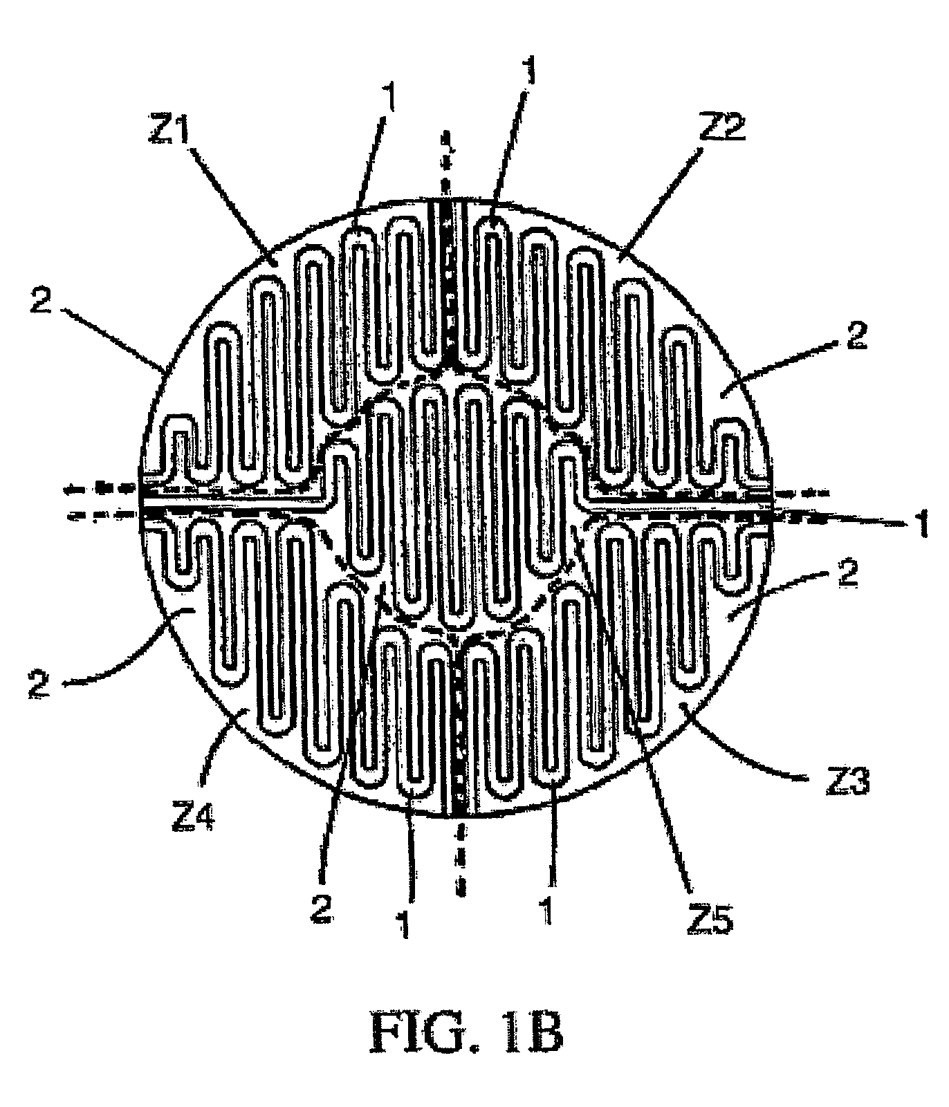
[0011]The present invention relates to a method of and a structure for quickly heating up an electrode (preferably a consumable electrode (e.g., a silicon, anodized aluminum or silicon carbide electrode) wherein the erosion of the electrode is sensitive to temperature) prior to the first wafer to be etched, and maintaining both a (temporally) stationary and a (spatially) homogeneous electrode temperature. This is accomplished by either embedding resistive heater elements within a housing containing an upper electrode or recessing resistive heater elements in the electrode so that the resistive heater elements (e.g., formed across multiple zones) are flush with the upper flat surface of the electrode. By preheating the electrode to the appropriate operating temperature, the “first wafer effect” can be eliminated along with its corresponding non-uniform etching of a semiconductor wafer. Further, by utilizing a multi-zone type heater, the temperature non-uniformity can be minimized.
[0012]A multi-zone heater embodiment of the present invention ameliorates both the first wafer effect and the non-uniform temperature effect of the electrode. The first wafer effect is ameliorated because the electrode is heated to the desired temperature prior to beginning to etch the first wafer. The non-uniform temperature is ameliorated because multi-zone heaters enable the power to each zone to be adjusted individually. Such a (multi-zone) heater can be achieved (1) using a heater integrated with the electrode or (2) using the electrode as a heater itself.

Problems solved by technology

The non-uniform temperature is ameliorated because multi-zone heaters enable the power to each zone to be adjusted individually.

Method used


Image

  • Method of and structure for controlling electrode temperature
  • Method of and structure for controlling electrode temperature
  • Method of and structure for controlling electrode temperature

Examples


first embodiment

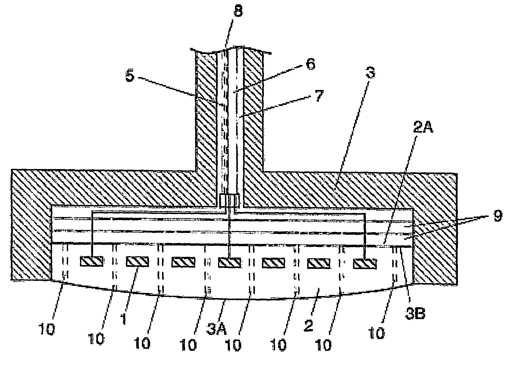
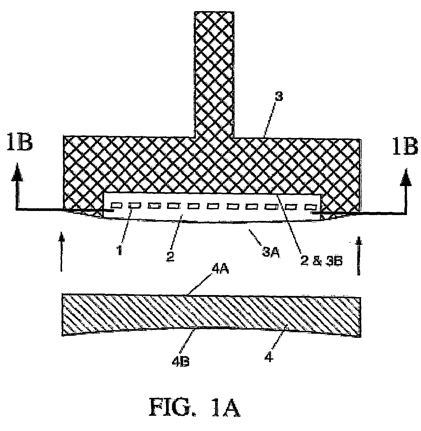
[0027]Referring to the drawing figures, like reference numerals designate identical or corresponding parts throughout the several views. FIG. 1A illustrates the present invention, in which resistive heater elements 1 are embedded in a plate 2 (e.g., made of quartz, alumina or generally an electrically insulating material that has a low coefficient of thermal expansion and is compatible with an etch process). In turn, the plate 2 is inset in and affixed to an electrode housing 3. The electrode housing 3 is made of metal (e.g., aluminum) and it is machined with an inset to receive the plate 2. Furthermore, the outer edge of electrode housing 3 is machined with a slight convexity in order to be flush with the convexity of the bottom surface 3A of plate 2. As stated, the plate 2 is machined so that a bottom surface 3A thereof has a slight convexity (e.g., approximately 0.025 to 2 millimeters). An electrode 4 (e.g., an electrode of any of: silicon, anodized aluminum, carbon and silicon c...

second embodiment

[0039]Due to the inherent physics of silicon as a semiconductor wafer, and depending on the doping level of the electrode, this system would have an absolute upper limit of operation of 300 C. (575 K). the present invention may have an operability issue because of the inherent upper limit of the operating temperature being about 300 C. as a result of the physics of using a semiconductor as a heater. However, the 300 C. upper limit is above the normally desired operating temperature and therefore, should not be a limitation.

[0040]As in the first embodiment, electrical connection of the DC power supplies to the resistive heater elements 1 are provided. Wires (not shown) are passed through the RF transmission feed 7 of the upper electrode housing 3 to contacts 16 located adjacent to the surface in contact with the electrode 4 as shown in FIG. 6. The contacts 16 and wires (not shown) are insulated from the surrounding conducting structure via insulation 17. A bolt 18 connecting the elec...


PUM

PropertyMeasurementUnit
Thicknessaaaaaaaaaa
Temperatureaaaaaaaaaa
Thicknessaaaaaaaaaa

Abstract

A method of and a structure for controlling the temperature of an electrode (4). The electrode is heated prior to etching the first wafer and both a (temporally) stationary and a (spatially) homogeneous temperature of the silicon electrode are maintained. Resistive heater elements (1) are either embedded within the housing of the electrode (3) or formed as part of the electrode. The resistive heater elements form a heater of a multi-zone type in order to minimize the temperature non-uniformity. The resistive heater elements are divided into a plurality of zones, wherein the power to each zone can be adjusted individually, allowing the desirable temperature uniformity of the electrode to be achieved. Preheating the electrode to the appropriate operating temperature eliminates both the “first wafer effect” and non-uniform etching of a semiconductor wafer.

Description

CROSS REFERENCE TO RELATED APPLICATIONS[0001]The present application is related to applications entitled “Multi-Zone Resistance Heater,” U.S. Provisional Ser. No. 60 / 156,595 filed Sep. 29, 1999; and PCT / US00 / 25503, entitled “Multi-Zone Resistance Heater,” filed Sep. 18, 2000. Each of those applications is herein incorporated by reference in its entirety.BACKGROUND OF THE INVENTION[0002]1. Field of the Invention[0003]The present invention generally relates to a method of and a system for controlling uniformity when etching semiconductor wafers, and more particularly to a method of and a system for controlling a temperature of an electrode (e.g., an electrode of any of: silicon, anodized aluminum, carbon and silicon carbide).[0004]2. Discussion of the Background[0005]Plasma systems for the etching of silicon process wafers are in widespread usage. In some embodiments, such plasma systems have an electrode plate attached to the upper electrode surface for two primary purposes: (1) to p...

Claims


Application Information

Patent Timeline
IPC IPC(8): B23K9/00H01J37/32H01L21/00
CPCH01J37/32724H01L21/67248H01L21/67109H01L21/67069
Inventor STRANG, ERIC J.MITROVIC, ANDREJFORDEMWALT, JIMJOHNSON, WAYNE L.
Owner TOKYO ELECTRON LTD
Learn More