
Mobile communication system and method for controlling receiving quality

Inactive Publication Date: 2006-07-04
NTT DOCOMO INC
View PDF22 Cites 20 Cited by
  • Summary
  • Abstract
  • Description
  • Claims
  • Application Information

AI Technical Summary

Benefits of technology

[0009]It is thus an object of the present invention to provide a mobile communication system that is adapted, in view of the above-described points, to improve the receiving quality compared to the prior art even if the instantaneous control of transmission power is not provided, as well as a method for controlling receiving quality in the mobile communication system.
[0010]To attain this object, the present invention increases or reduces the number of base stations to simultaneously connect to a mobile station so as to realize a certain level of receiving quality control even if instantaneous control of transmission power is not executed, on the basis of the fact that when a plurality of received signals are synthesized, a variation in the level of the received signals decreases.
[0016]The quality control means has means for measuring traffic in cells surrounding a cell in which the mobile station is present and means for requesting the network control station to transmit a duplicate signal to one or more stations, if any, which have a lower measured traffic and which can transmit information to the mobile station communicating in an adjacent cell. The mobile station receives and synthesizes signals from base stations that have been communicating with the mobile station and from the one or more base stations, thereby improving the downlink receiving quality.
[0022]The quality control means measures traffic in cells surrounding a cell in which the mobile station is present, and requests the network control station to transmit a duplicate signal to one or more base stations, if any, which have a lower measured traffic and which can transmit information to the mobile station communicating in an adjacent cell. The mobile station receives and synthesizes signals from base stations that have been communicating with the mobile station and from the one or more base stations, thereby improving the downlink receiving quality.
[0023]A fifth aspect of the present invention provides a recording medium having a receiving quality control program for a mobile communication system recorded therein, the mobile communication system having a plurality of base stations within a service area, the program allowing execution of a step of causing a network control station to duplicate and / or synthesize information in order to allow a mobile station to simultaneously communicate with at least two base stations.
[0025]According to the present invention, even if instantaneous control of transmission power is not executed, the receiving quality can be improved compared to the prior art. In other words, the present invention increases or reduces the number of base stations to simultaneously connect to a mobile station so as to realize a certain level of receiving quality control even if instantaneous control of transmission power is not executed, on the basis of the fact that when a plurality of received signals are synthesized, a variation in the level of the received signals decreases.

Problems solved by technology

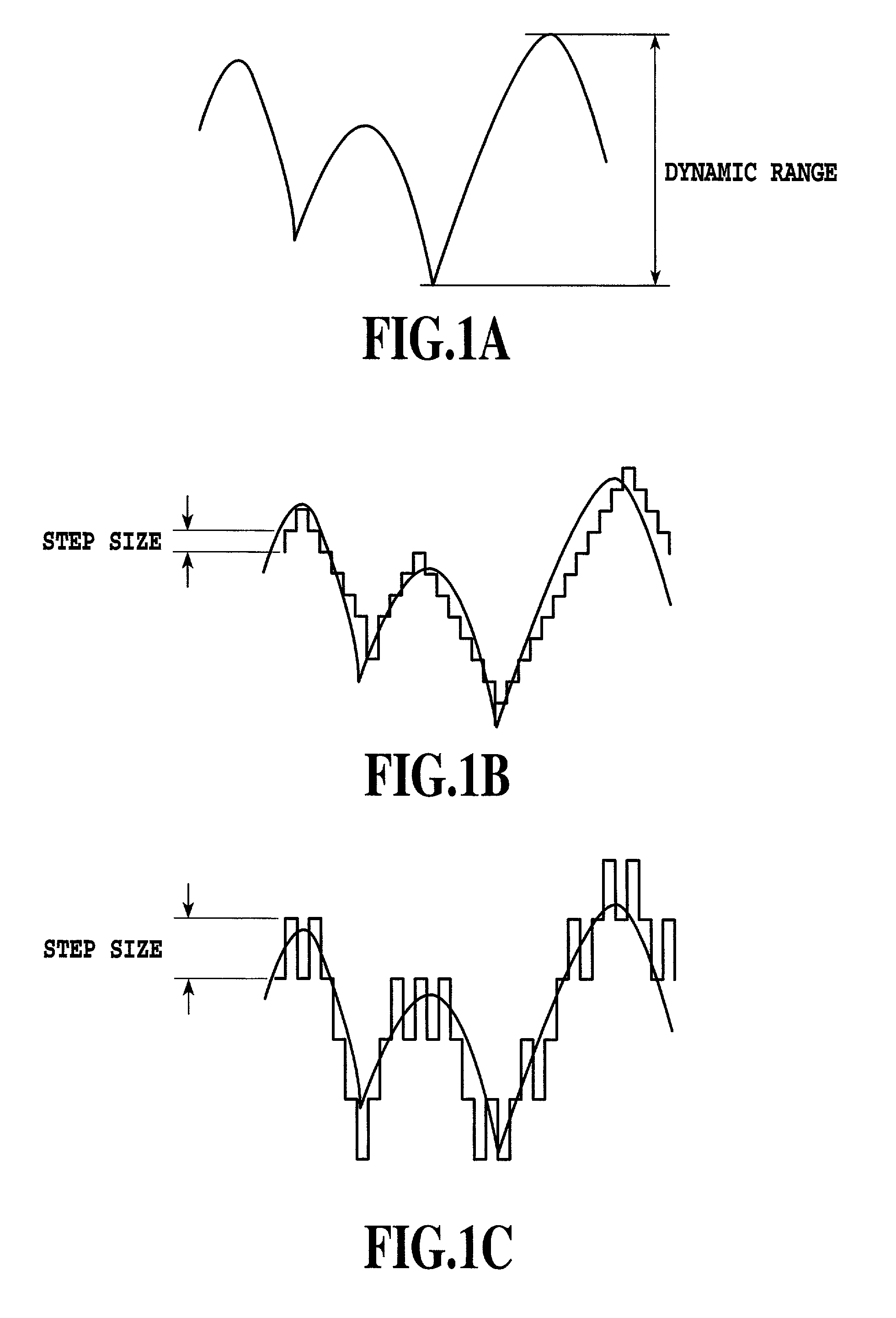
FIGS. 1A to 1C show problems with receiving quality control using conventional transmission power control.
In this case, if the transmission power is controlled by a small step size (see FIG. 1B), transmission power control cannot follow rapid variations in receiving level.
On the other hand, if the transmission power is controlled by a large step size (see FIG. 1C), transmission power control cannot accurately follow variations in receiving level.
In this case, a new problem occurs; the overhead of a control signal for the transmission power control may reduce transmission efficiency.
Consequently, it is difficult to apply an efficient power amplifier.

Method used


Image

  • Mobile communication system and method for controlling receiving quality
  • Mobile communication system and method for controlling receiving quality
  • Mobile communication system and method for controlling receiving quality

Examples


embodiment 1

[Embodiment 1]

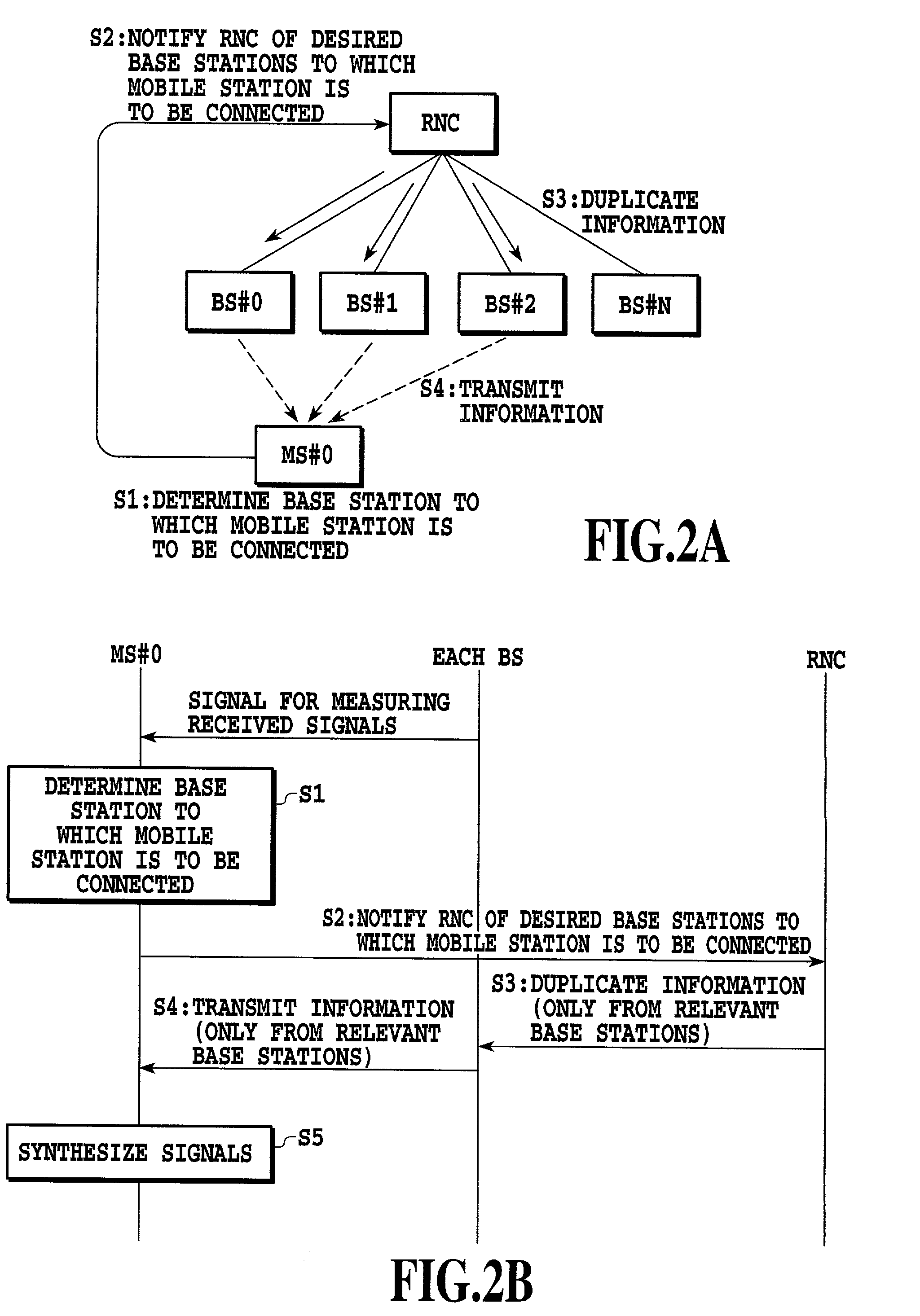
[0044]FIG. 2A shows a mobile communication system for implementing receiving quality control for a downlink. In this figure, reference characters RNC, BS, and MS denote a radio network controller, a base station, and a mobile station, respectively. More specifically, FIG. 2A shows how the base station BS (including base stations #0 to #N), the mobile station MS#0, and the radio network control station RNC are connected together according to Embodiment 1, and FIG. 2B shows the flow of communication control according to Embodiment 1.

[0045]In Embodiment 1, the mobile station MS#0 measures power received from surrounding base stations to determine to which base stations it is to be connected in order to satisfy a desired downlink receiving quality (step S1).

[0046]The mobile station MS#0 notifies the radio network control station RNC of the desired base stations to which it is to be connected, using the signal format shown in FIG. 3 (step S2). FIG. 3 shows the signal format...

embodiment 2

[Embodiment 2]

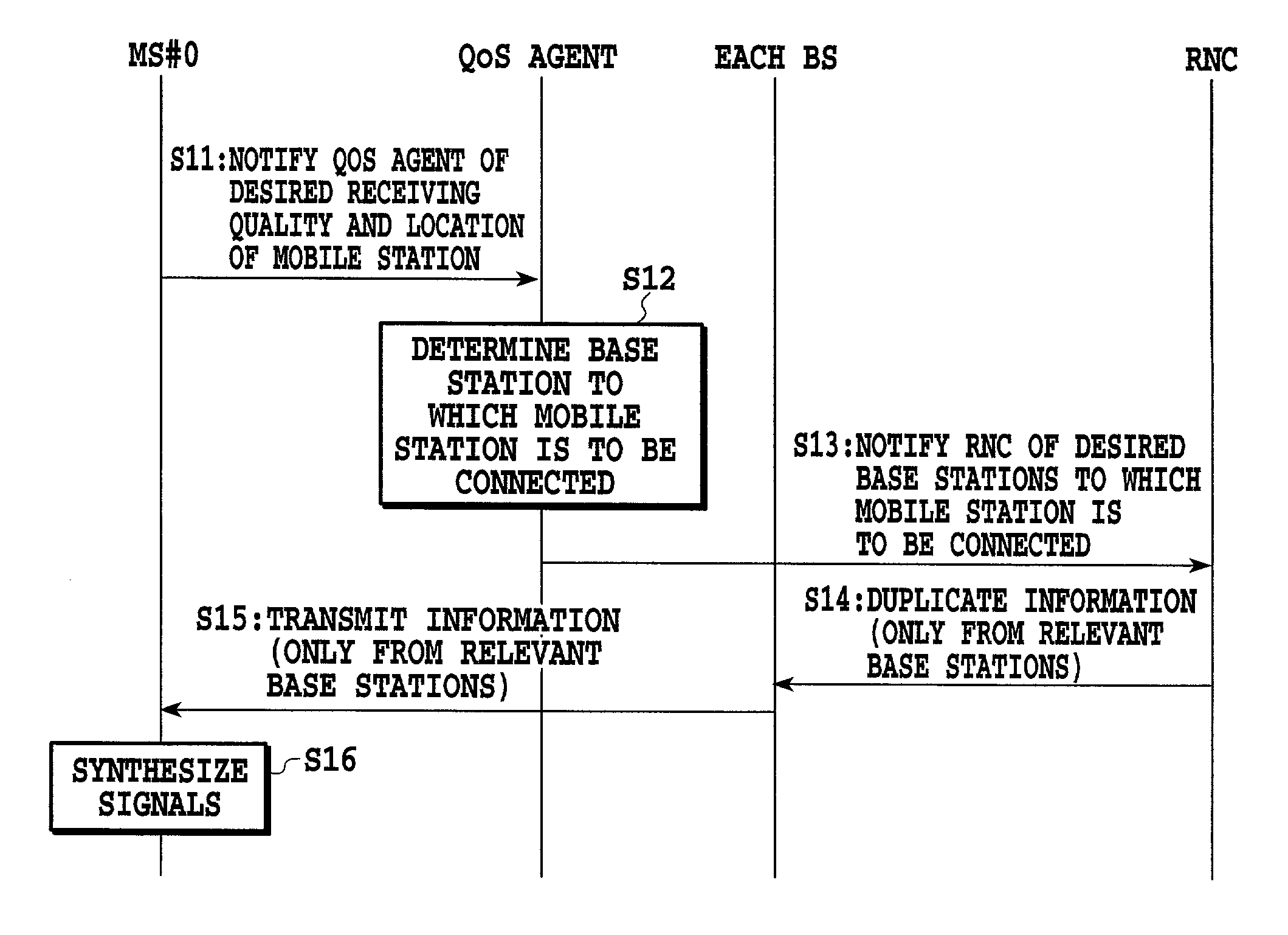
[0050]FIG. 4A shows another mobile communication system for implementing receiving quality control for the downlink. This system comprises a QoS (Quality of Service) agent in addition to the radio network control station RNC, the base station BS, and the mobile station MS. More specifically, FIG. 4A shows how the base station BS (including base stations #0 to #N), the mobile station MS#0, the radio network control station RNC, and the QoS agent are connected together according to Embodiment 2, and FIG. 4B shows the flow of communication control according to Embodiment 2.

[0051]In Embodiment 2, the mobile station MS#0 notifies the QoS agent of a downlink receiving quality desired thereby and the location thereof, using the signal format shown in FIG. 5A (step S11). FIG. 5A shows the signal format used by the mobile station MS#0 to notify the QoS agent (=signal indicative of a desired receiving quality and information on the location of the mobile station). This signal fo...

embodiment 3

[Embodiment 3]

[0059]FIG. 8A shows a mobile communication system for implementing receiving quality control for an uplink. This system comprises the radio network control station RNC, the base station BS, the mobile station MS, and the QoS agent. More specifically, FIG. 8A shows how the base station BS (including base stations #0 to #N), the mobile station MS#0, the radio network control station RNC, and the QoS agent are connected together according to Embodiment 3, and FIG. 8B shows the flow of communication control according to Embodiment 3.

[0060]In Embodiment 3, before transmitting information, the mobile station MS#0 transmits a desired uplink quality received by base stations and the location and transmittable maximum power of the mobile station, to the QoS agent using the signal format shown in FIG. 9A (step S41). The QoS agent selects base stations to which the mobile station is to be connected in order to satisfy this quality in such a way that the transmittable maximum powe...


PUM


Abstract

The present invention improves receiving quality compared to the prior art even if instantaneous control of transmission power is not executed. A mobile station MS#0 measures signal level received from surrounding base stations and determines to which base stations it is to be connected in order to satisfy a desired downlink receiving quality (step S1). The mobile station MS#0 notifies a radio network control station RNC of the desired based stations to which the mobile station is to be connected (step S2). Upon receiving the notification from the mobile station MS#0, the radio network control station RNC duplicates a downlink transmitted signal for the mobile station MS#0, if any, and transmits it to the selected base stations (step S3). The mobile station MS#0 receives signals transmitted by the base stations (step S4) and synthesizes these signals (step 5), thereby satisfying the desired downlink receiving quality.

Description

[0001]This application claims priority under 35 U.S.C. 119 to Patent Application No. 2000-347124 filed Nov. 14, 2000 in Japan, the content of which is incorporated hereinto by reference.BACKGROUND OF THE INVENTION[0002]1. Filed of the Invention[0003]The present invention relates to a mobile communication system and a method for controlling receiving quality in the mobile communication system. More specifically, the present invention relates to a mobile communication system that provides communication services from a base station to a mobile station via a radio channel and a method for controlling receiving quality in the mobile communication system.[0004]2. Description of the Related Art[0005]In a known mobile communication system, a desired receiving quality is achieved mainly by controlling transmission power to compensate for an instantaneous variation in received signal level.[0006]FIGS. 1A to 1C show problems with receiving quality control using conventional transmission power ...

Claims


Application Information

Patent Timeline
IPC IPC(8): H04Q7/20H04B7/26H04B7/005H04B7/02H04W52/40
CPCH04W52/40H04B7/022H04W28/24H04W48/20H04W52/04
Inventor IKEDA, TAKEHIROOKAJIMA, ICHIROUMEDA, NARUMI
Owner NTT DOCOMO INC
Learn More