Hybrid construction equipment power control apparatus

Active Publication Date: 2006-07-04
KOBE STEEL LTD +1
View PDF17 Cites 50 Cited by
  • Summary
  • Abstract
  • Description
  • Claims
  • Application Information

AI Technical Summary

Benefits of technology

[0006]Accordingly, an object of the present invention is to provide a power controller for hybrid construction machine which makes it possible to prevent performance deterioration of its battery due to charging / discharging over the battery capacity as well as to improve fuel consumption of its engine. It is another object of the present invention to provide a power controller for hybrid construction machine, which makes it possible to improve fuel consumption of its engine.

Problems solved by technology

However, known construction machine using engine as power source suffer from problems in that they burn too much gas due to large load fluctuation and inordinate burden to the engine, and that they generate noise and / or exhaust gas emissions.
However, the foregoing state-of-charge SOC based control have suffered from the problem in that halting generator, or reducing the output of the generator caused drop of efficiencies of engine and generator in case of small load and high state-of-charge SOC.
In addition, the foregoing state-of-charge SOC based control in the same case above have also suffer from the problem in that there might be a situation that electric actuators might not be supplied with electric power required for its operation because of time-lag to restart engine once halted, and it was required to increase battery capacity to overcome the problem.
Therefore, it was difficult to achieve the conditions simultaneously of supplying appropriate electric power required for electric actuator, controlling battery state-of-charge, operating engine and generator highly efficiently.
For example, if it was prioritized to operate engine and generator highly efficiently, battery capacity was resulted in increase in case of small load of electric actuator, and therefore it was difficult to control battery state-of-charge SOC within a specified range.
In contrast, if it was prioritized to control battery state-of-charge SOC within a specified range, output power fluctuation due to load fluctuation of engine and generator was resulted in increase, and therefore efficiencies of engine and generator drop.
In addition, charging / discharging over battery capacity in case of low battery temperature would have been likely to cause the performance deterioration of the battery because of battery characteristics that charging / discharging capacity depend on its temperature.
Further, controlling only based on battery state-of-charge SOC would have been likely to cause the increase of loss because losses of battery and generator vary with output powers of generator and battery respectively while internal loss of battery varies with input power of the battery.

Method used


Image

  • Hybrid construction equipment power control apparatus
  • Hybrid construction equipment power control apparatus
  • Hybrid construction equipment power control apparatus

Examples


first embodiment

[0032

[0033]A power controller for hybrid excavator according to a first embodiment of the present invention will be described below referring to the accompanying drawings.

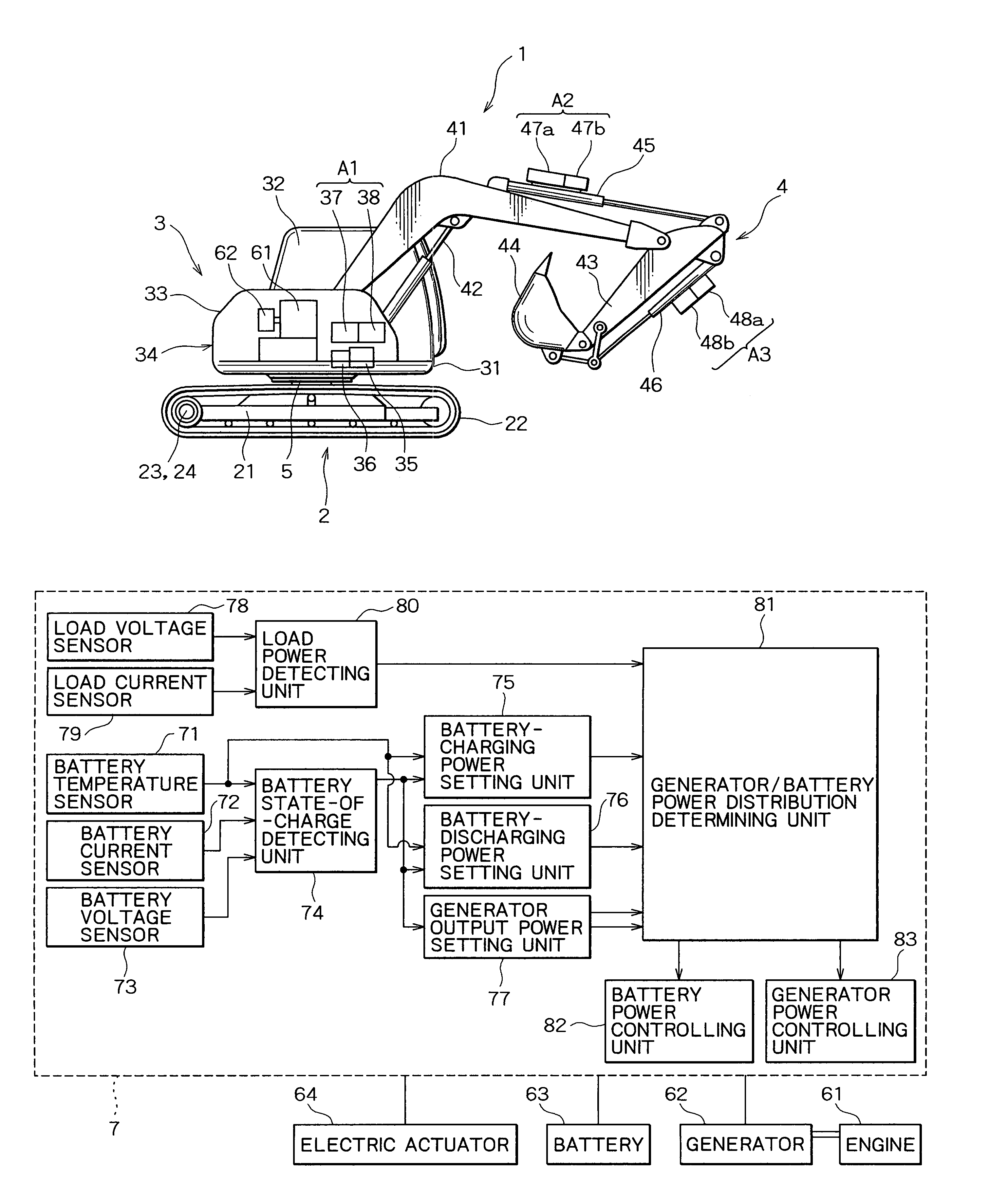
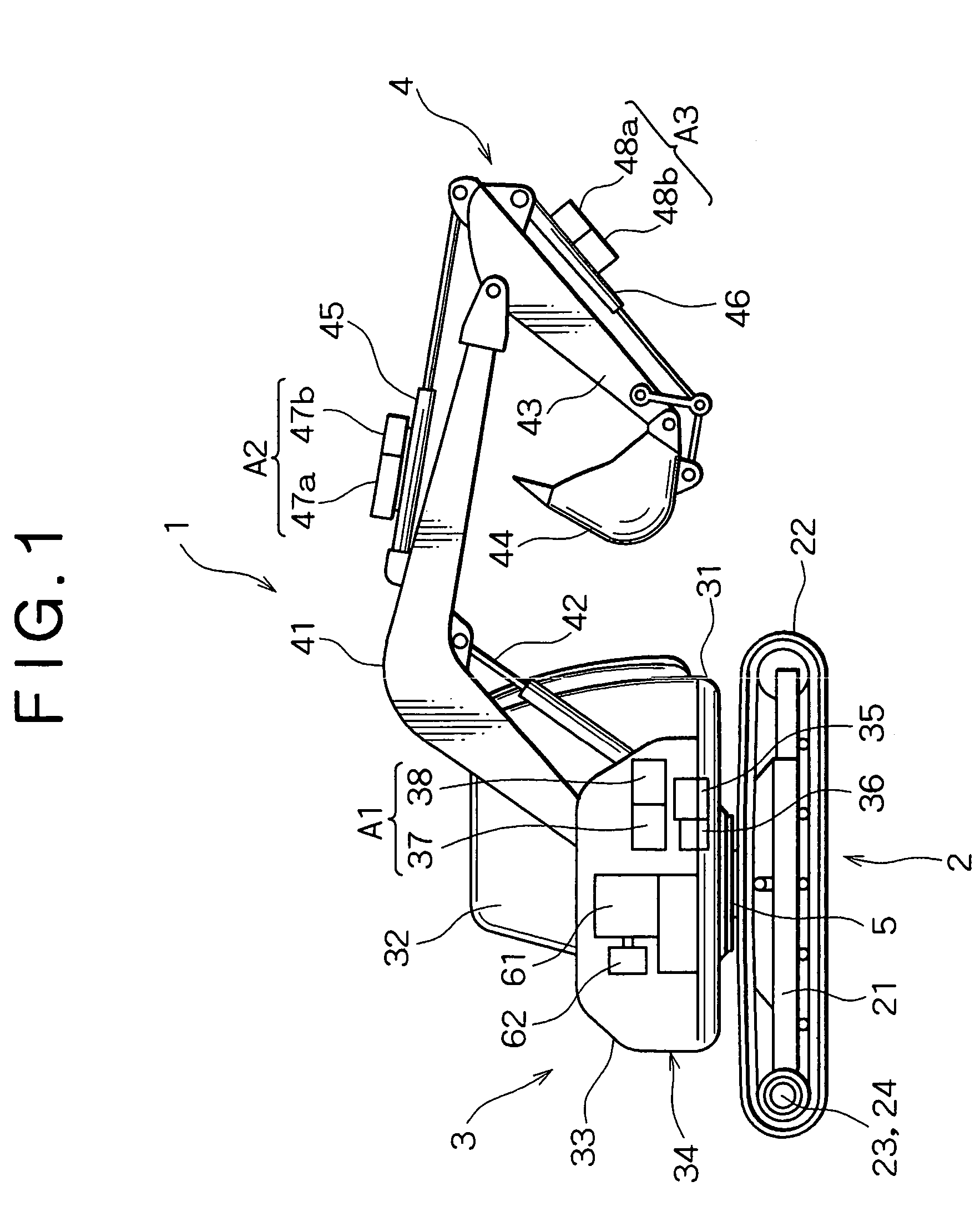
[0034]At first, a hybrid excavator to which a power controller according to the first embodiment is applied will be described referring to FIG. 1. It should be noted that FIG. 1 is a view showing a frame format of an outline configuration of a hybrid excavator.

[0035]In FIG. 1, a hybrid excavator 1 comprises a lower traveling body 2, an upper rotating body 3 which is connected rotatably to the center portion of the upper surface of the lower traveling body 2, and an excavating attachment 4 which is connected to the front portion of the upper rotating body 3.

[0036]The lower traveling body 2 includes a pair of crawler frames 21 arranged at the both ends in parallel, a crawler 22 configured rotatably around each crawler frame 21 to contact on the ground surface planarly, a motion reducer 23 and a motor 24 to drive in r...

second embodiment

[0084

[0085]A power controller for hybrid excavator according to a second embodiment of the present invention will be described below referring to the accompanying drawings. The hybrid excavator 1 in the first embodiment described using FIG. 1 is available as a hybrid excavator to which a power controller according to the second embodiment is applied.

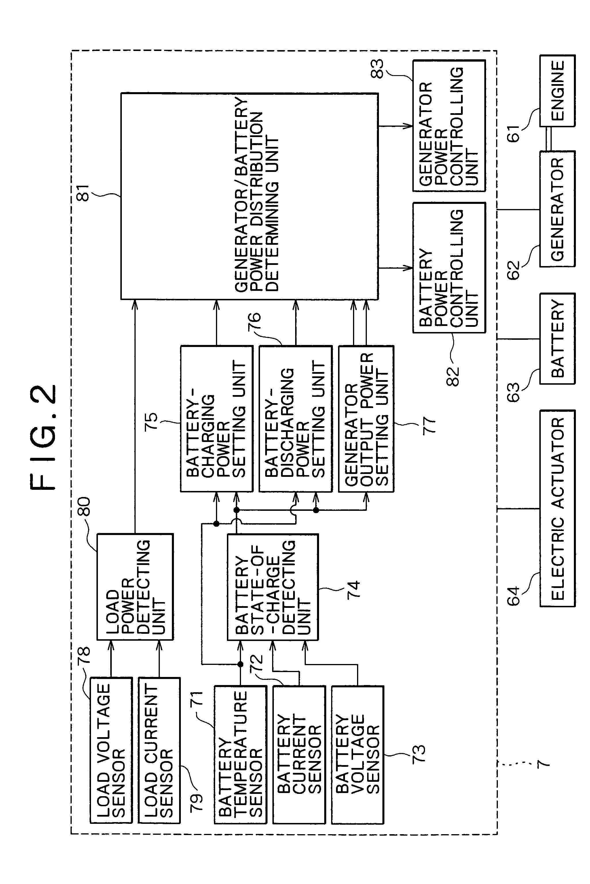
[0086]At first, a power controlling mechanism of a hybrid excavator according to the second embodiment will be described referring to FIG. 10. It should be noted that FIG. 10 is a block diagram illustrating a power controlling mechanism according to the second embodiment. Elements substantially equal to those in the first embodiment are provided with the same symbols.

[0087]The block diagram shown in FIG. 10 consists of an engine 61, a generator 62, a battery 63, an electric actuator 64, and a power controlling mechanism 9. Power supply from the battery 63 to the electric actuator 64 and that from the generator 62 to the electric actuator...


PUM


Abstract

Maximum charging power of a battery (63) is set by a battery-charging power setting unit (75), while maximum discharging power of the battery (63) is set by a battery-discharging power setting unit (76). Lower and upper limit of generator output power is set by a generator output power setting unit (77). A generator / battery power distribution determining unit (81) distributes power between the battery (63) and the generator (62) using the set values above.

Description

TECHNICAL FIELD[0001]The present invention relates to a power controller for controlling output power of generator and charging / discharging power of electrical energy storage unit, both installed in hybrid construction machine.BACKGROUND ART[0002]Engine for self-traveling has been installed in construction machine such as hydraulic excavators and the like, the engine operating as a power source to drive hydraulic pump and supply each hydraulic actuator such as rotating actuators, boom cylinders, arm cylinders etc. with hydraulic oil discharged from the hydraulic pump, to drive each portion. However, known construction machine using engine as power source suffer from problems in that they burn too much gas due to large load fluctuation and inordinate burden to the engine, and that they generate noise and / or exhaust gas emissions. Accordingly, hybrid construction machine containing motors driven by combination of generator and electrical energy storage unit (battery) have been develop...

Claims


Application Information

Patent Timeline
IPC IPC(8): E02F5/02G05D1/02B60L11/18B60L50/15B60L50/16B60W10/26B60W20/00E02F9/20H02J7/00H02J7/14H02J7/16H02J7/34
CPCB60K6/12B60L3/0046B60L11/14B60L11/1851B60L11/1859B60L11/1862B60L11/187B60L11/1872B60W10/08B60W10/26E02F9/20E02F9/2025H02J7/1415H02J7/1453H02J7/1461H02J7/1492B60L1/003Y02T10/70B60L2240/423B60W20/00B60W2510/244B60W2510/246B60W2710/083B60Y2200/412Y02T10/6208Y02T10/7005Y02T10/7044Y02T10/705Y02T10/7077Y02T10/642E02F9/2075E02F9/2091B60L50/16B60L58/10B60L58/13B60L58/24B60L58/25H02J7/007194Y02T10/62Y02T10/64Y02T10/7072H02J7/0048B60W20/13B60K6/28B60W2300/17B60W10/24B60W2510/24B60W2710/24
Inventor KAGOSHIMA, MASAYUKISORA, TOSHIOKOMIYAMA, MASAYUKI
Owner KOBE STEEL LTD
Why Eureka
Try Eureka