
Power amplifier module with distortion compensation

a power amplifier and compensation circuit technology, applied in the direction of amplifiers, amplifiers with semiconductor devices/discharge tubes, negative-feedback circuit arrangements, etc., can solve the problems of gross noise and distortion components, inherent internal non-linearities, and compensation is the amount of circuitry required for compensation, etc., to reduce non-linear distortion, minimal additional circuitry, cost-effective

Inactive Publication Date: 2006-06-27
NXP BV
View PDF2 Cites 67 Cited by
  • Summary
  • Abstract
  • Description
  • Claims
  • Application Information

AI Technical Summary

Benefits of technology

The present invention provides an improved power amplified module that overcomes the disadvantages of prior art. It features distortion compensation by making use of the fact that the outputs of opposite sides of a Bridge Tied Load configuration conduct substantially the same currents at any given moment. The invention is especially applicable in BiMos processes, like Philips Semiconductors ABCD process. It reduces non-linear distortions caused by power amplification in the class AB or B mode and provides accurate compensation regardless of the load that is applied between both output nodes. The invention can be used for mains fed applications, e.g. TV sound, PC audio, portable audio, car audio systems and all other kinds of audio and sound systems.

Problems solved by technology

The errors involved, however, are the gross noise and distortion components for which typical compensating networks suffice as the error generator, and not the inherent internal non-linearities of elements themselves.
A common disadvantage of the presented power amplifiers with feedforward distortion compensation is the amount of circuitry required for the compensation.
Another common disadvantage is that the compensation is accurate for only one type of load.

Method used


Image

  • Power amplifier module with distortion compensation
  • Power amplifier module with distortion compensation
  • Power amplifier module with distortion compensation

Examples


Embodiment Construction

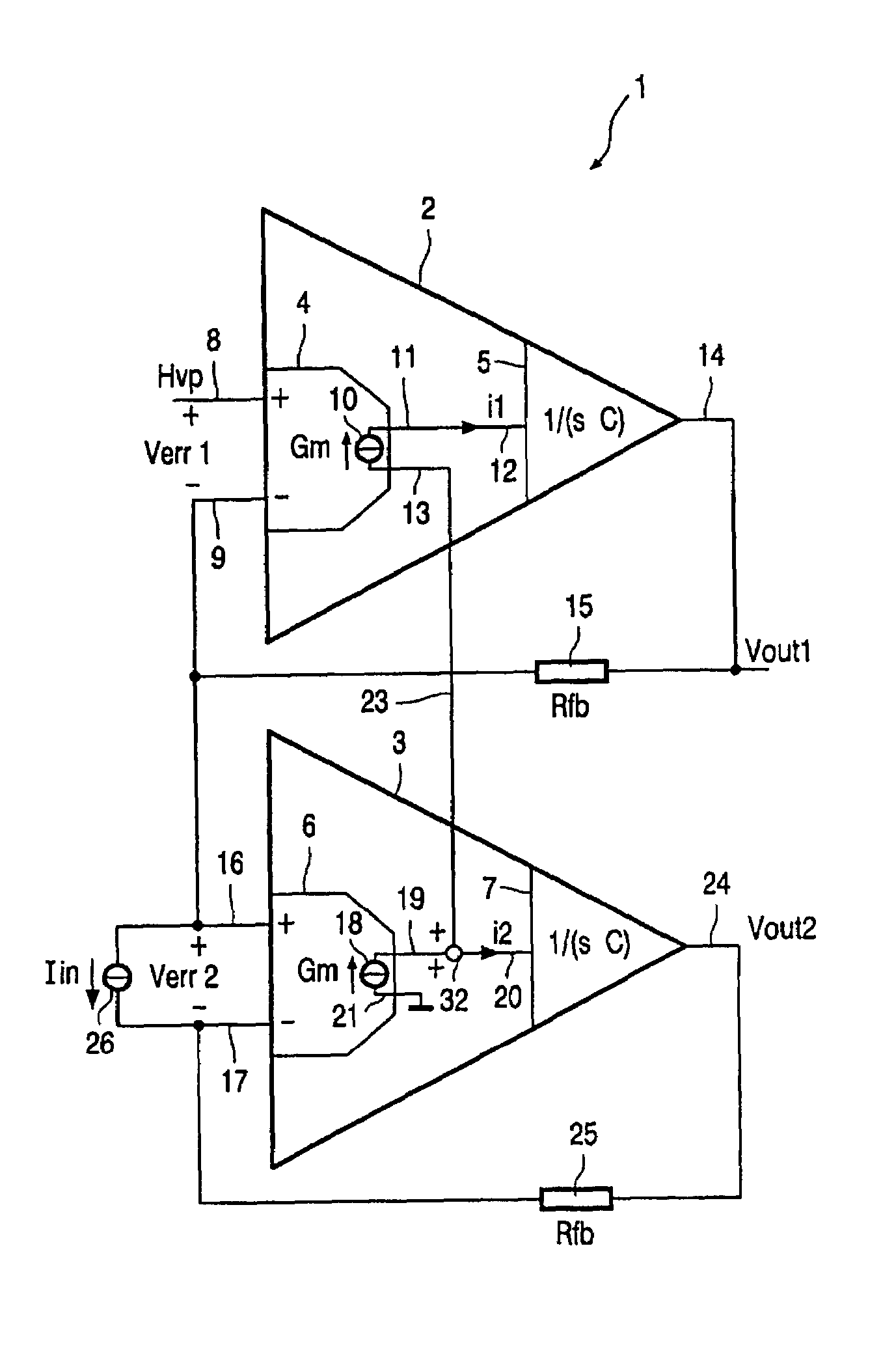
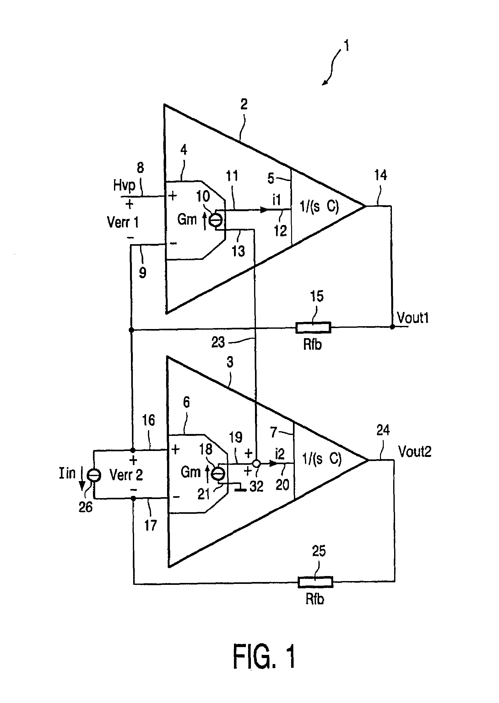
[0028]FIG. 1 shows an embodiment of an amplifier module 1 in accordance with the invention. In the preferred embodiment considered here the amplifier module 1 is an integrated circuit which is realized on a single integrated circuit chip.

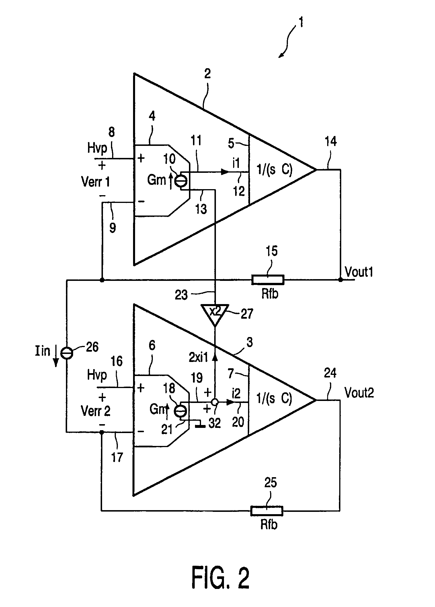
[0029]The amplifier module 1 comprises an amplifier 2 and an amplifier 3. The amplifier 2 has a front-end amplifier stage 4 and a backend amplifier stage 5. Likewise the amplifier 3 has front-end amplifier stage 6 and backend amplifier stage 7.

[0030]The front-end amplifier stage 4 has a non-inverting input terminal 8 and an inverting input terminal 9. The non-inverting input terminal 8 serves for application of a reference voltage Hvp, which normally has a value of half of the power supply voltage. The voltage across the non-inverting input terminal 8 and the inverting input terminal 9 is the error voltage Verr1.

[0031]The front-end amplifier stage 4 depicted in FIG. 1 is modelled by an operational transconductance amplifier with a transconductance G...


PUM


Abstract

The invention relates to a power amplifier module comprising a first amplifier 2 having a first front-end 4 and a first backend amplifier stage 5 and a second amplifier 3 having a second front-end 6 and a second backend amplifier stage 7, the first amplifier and the second amplifier being arranged in a Bridge Tied Load (BTL) configuration with feedback over the load,characterized in thatthe first and the second backend amplifier stages having point symmetrical transfer functions with respect to the origin,the input current i1 of the first backend amplifier stage being substantially equal to the input current i2 of the second backend amplifier stage.

Description

FIELD OF THE INVENTION[0001]The invention relates to a power amplifier module and in particular to an audio or high frequency power amplifier, and more particularly to reducing distortion of an amplifier stage.BACKGROUND AND PRIOR ART[0002]In most audio amplifiers distortion dominantly originates from the non-linear class AB or B biased elements. Generally the backend power amplifier stages operate in class AB or B mode.[0003]Local feedback can be used to minimize the non-linear nature of the input-output transfer characteristic. To further improve the overall linearity it is known to employ a technique of overall negative feedback which is used to achieve the gain stability requirements.[0004]Feedforward is also employed, and it is to be noted that U.S. Pat. No. 4,379,994 suggests the inclusion of an error-generating device to correct for some characteristics of an amplifier, based upon a feedforward circuit and another amplifier. The errors involved, however, are the gross noise a...

Claims


Application Information

Patent Timeline
Patent Type & Authority Patents(United States)
IPC IPC(8): H03F1/34H03F3/68H03F3/30
CPCH03F3/3081H03F3/30
Inventor VERSTEEGEN, MARIUS GERARDUS JACOBUS
Owner NXP BV
Learn More