
Magnetic sensor digital processing interface for electrical motor application

Inactive Publication Date: 2006-06-20
DIALOG SEMICONDUCTOR GMBH
View PDF17 Cites 18 Cited by
  • Summary
  • Abstract
  • Description
  • Claims
  • Application Information

AI Technical Summary

Benefits of technology

[0012]A further object of the present invention is to achieve a system and a method for an interface for magnetic sensors to determine continuously rotational angles having a single sensor system and a flexible signal processing.

Problems solved by technology

Hall sensors have the disadvantage that they can detect a single position of a magnetic field only; therefore multiple Hall sensors are required to determine an angle velocity or in other words, a movement of devices.

Method used


Image

  • Magnetic sensor digital processing interface for electrical motor application
  • Magnetic sensor digital processing interface for electrical motor application
  • Magnetic sensor digital processing interface for electrical motor application

Examples


Embodiment Construction

[0022]The preferred embodiments disclose a system to determine continuously angle positions including an angle velocity calculation using anisotropic magnetoresistive (AMR) sensors.

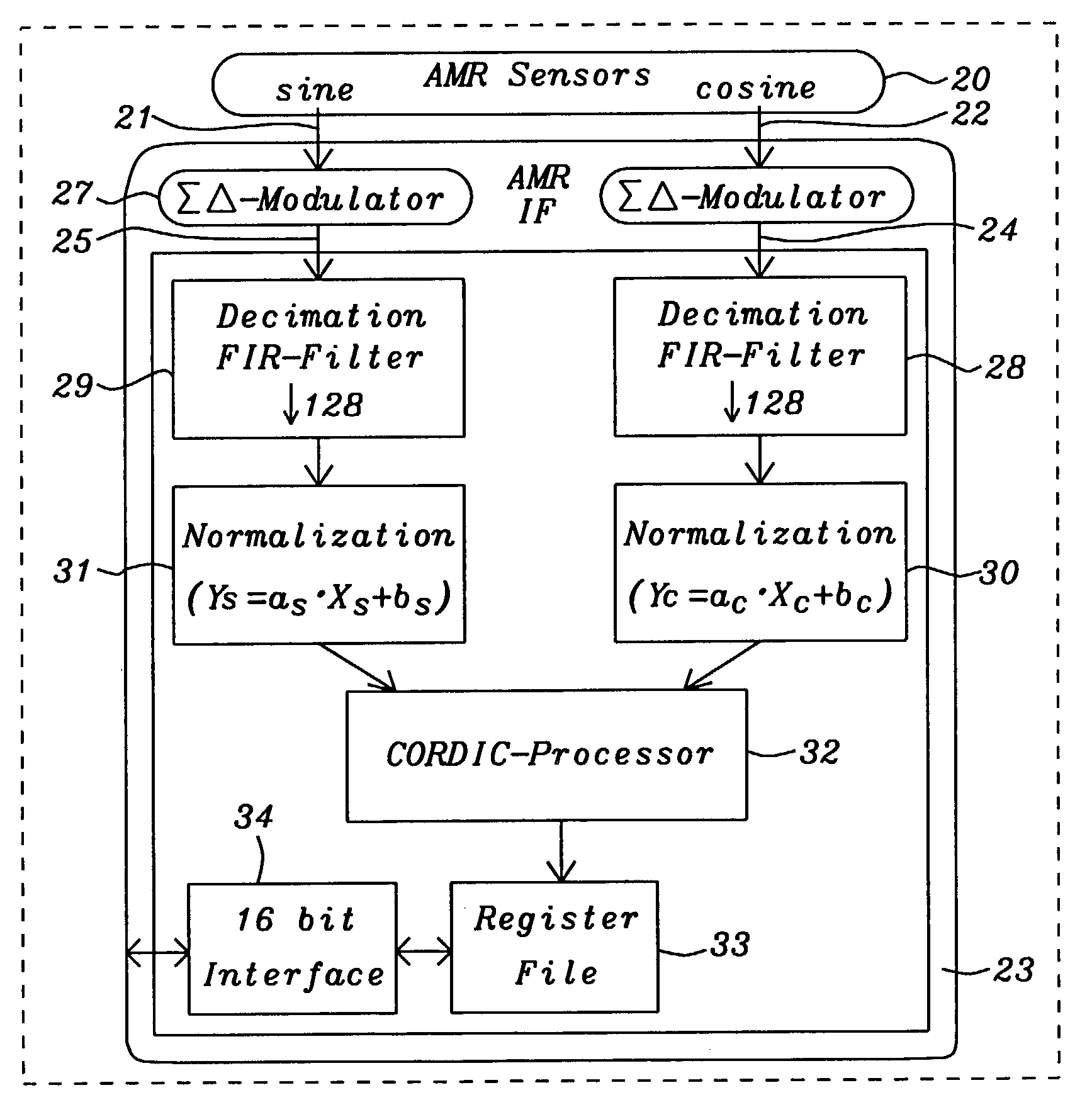
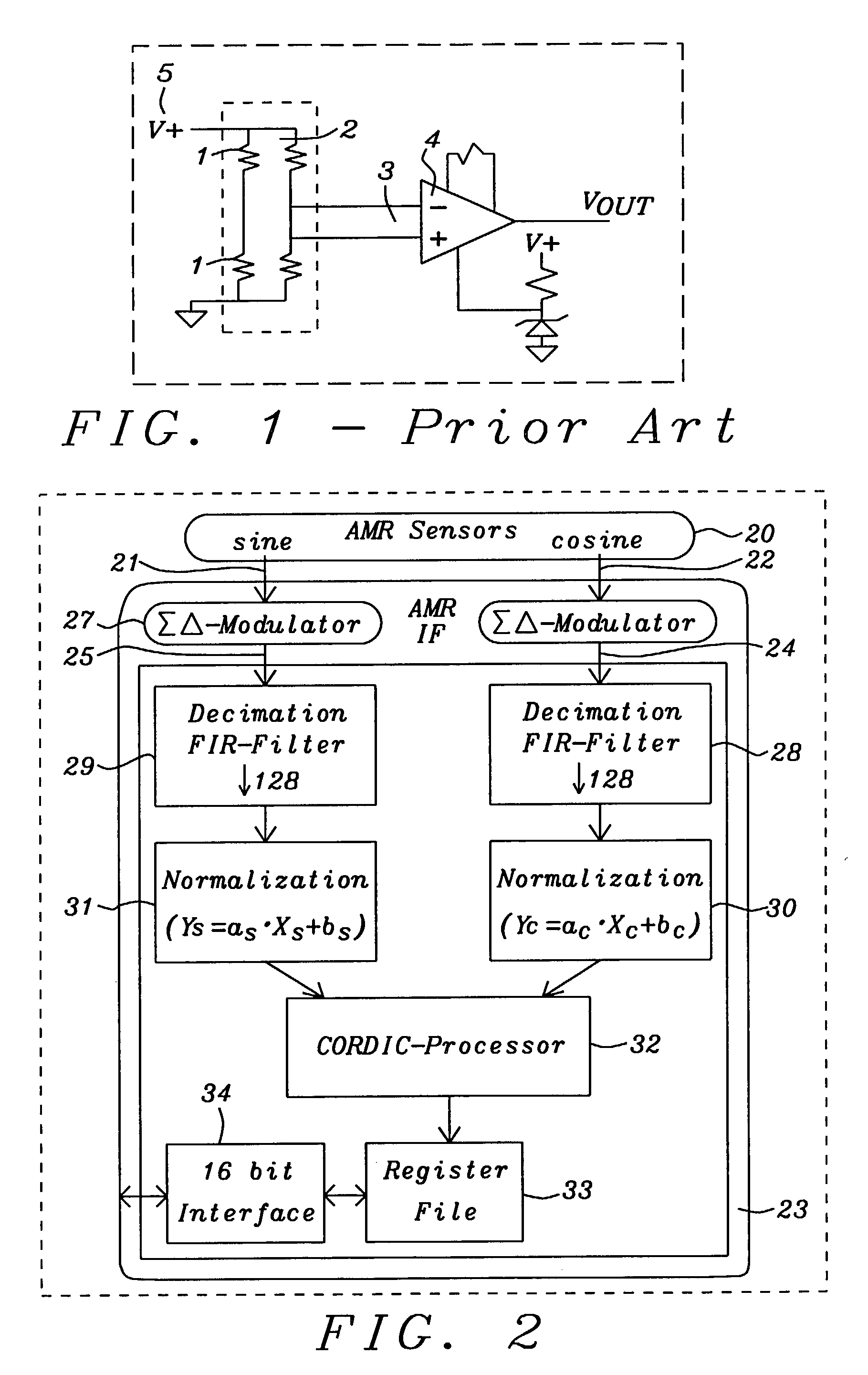
[0023]FIG. 2 shows a functional block diagram of a preferred embodiment of the AMR sensor interface 23 invented. Details of the components of said interface will be described later. Said interface calculates an angle position by means of the sine 21 and cosine 22 signals. Said interface 23 is receiving sine and cosine values of the position to be measured from AMR sensors 20 connected in a Wheatstone bridge.

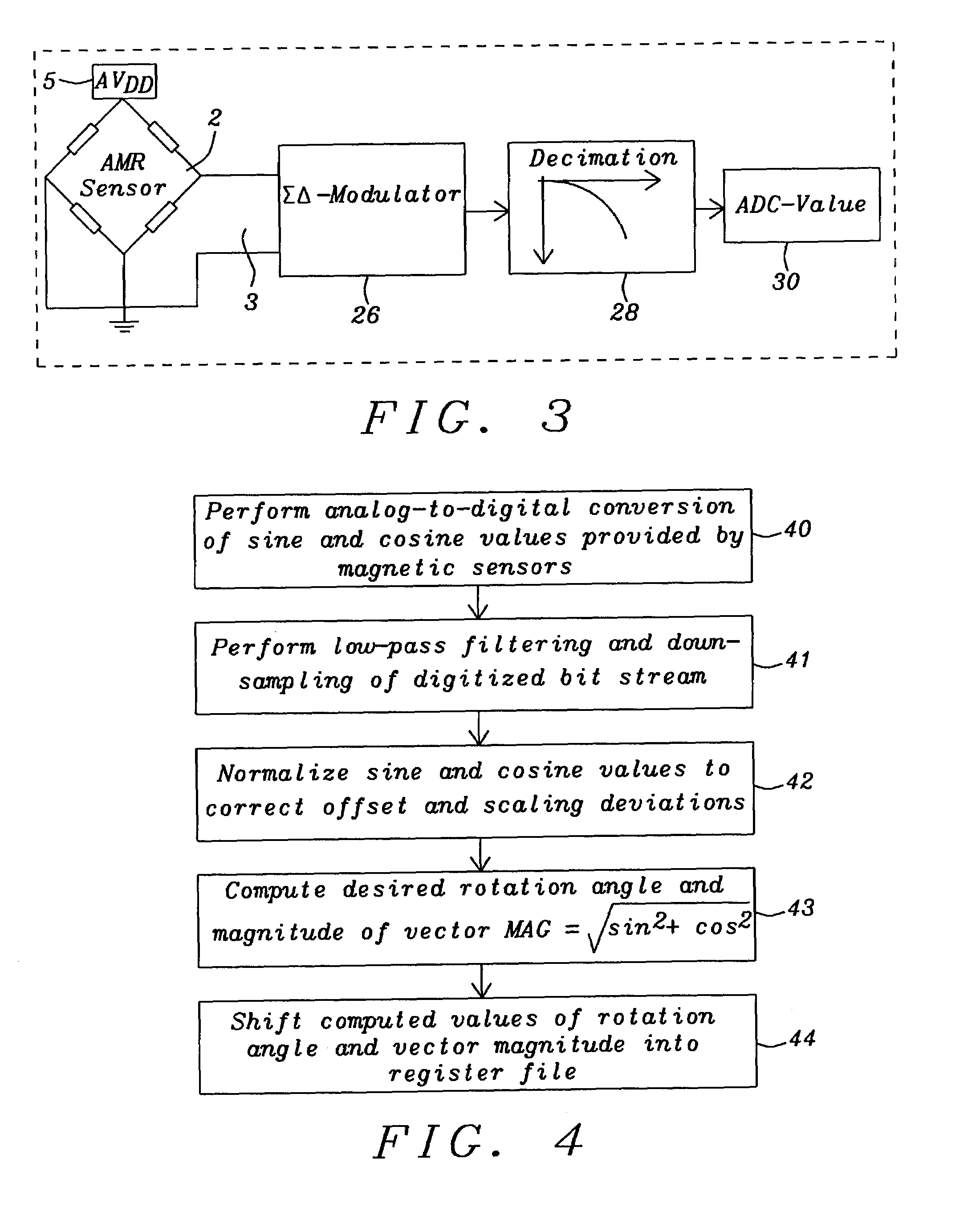
[0024]Two independent paths 24 and 25 are provided to process said sine 21 and cosine 22 signals. Said two paths 24 and 25 are closely synchronized. Said sine and cosine values are converted from analog to digital values using two second order delta sigma modulators 26 and 27. A pair of low-pass decimation filters 28 and 29 performs the digital value computation converting the bit stream of the delta s...


PUM


Abstract

A system and methods for an interface for magnetic sensors to determine a rotational angle has been achieved. This interface can be used for magnetic sensors providing analog signals of the sine and cosine values of the angle to be determined. Analog signals are being processed in two measurement paths for the sine and cosine signal each until the desired angle is computed by a CORDIC processor. The first stage of the measurement path is the conversion of the sine and cosine signals from analog to digital by 2nd order delta-sigma modulators with an over-sampling ratio. A low-pass decimation filter with sinc3 characteristic performs the digital value computation. The next stage normalizes the digitized sine and cosine values to correct offset and scaling deviations. The CORDIC processor computes the angle by decomposing the desired rotation angle into iterations of pre-defined elementary rotation angles performing the rotation operation by simple shift-and-add operations and the magnitude of the vector using the output from the normalization stages.

Description

BACKGROUND OF THE INVENTION[0001](1) Field of the Invention[0002]The present invention relates generally to measuring devices for contactless, continuous determination of relative angular position, and more particularly, to an anisotropic magnetoresistive (AMR) sensor interface providing a continuous rotational angle detection including a angle velocity calculation.[0003](2) Description of the Prior Art[0004]In prior art Hall sensors are often used to determine angular positions, as e.g. in automotive applications the movement and speed of an accelerator or the speed and direction of a driving shaft, etc. Hall sensors have the disadvantage that they can detect a single position of a magnetic field only; therefore multiple Hall sensors are required to determine an angle velocity or in other words, a movement of devices.[0005]Anisotropic magnetoresistive (AMR) sensors are more flexible and sensitive compared to Hall sensors. They are made of a nickel-iron (Permalloy) thin film deposit...

Claims


Application Information

Patent Timeline
Patent Type & Authority Patents(United States)
IPC IPC(8): G01B7/30G01D5/244
CPCG01D5/24404
Inventor KERNHOF, JUERGEN
Owner DIALOG SEMICONDUCTOR GMBH
Learn More