Upper bearing support assembly for internal turret

a technology for supporting assemblies and internal turrets, which is applied in the direction of special-purpose vessels, buoys, vessel construction, etc., can solve the problems of affecting the operation of the turret mooring system, damage to the upper bearing assembly, and hogging and sag of the vessel

Active Publication Date: 2006-06-20
SOFEC
View PDF28 Cites 14 Cited by
  • Summary
  • Abstract
  • Description
  • Claims
  • Application Information

AI Technical Summary

Benefits of technology

[0007]Since the lower ring of the upper bearing support assembly is located near the vertical center of the vessel, only minimal deflections of the vessel will be transmitted to the upper bearing assembly through the support beams. In addition, because the support beams will deflect and allow the turret to pivot, the pivoting of the turret will not adversely affect the upper bearing assembly. Thus, the upper bearing support assembly of the present invention provides an effective means to isolate the upper bearing assembly from both the deflections of the vessel and the pivoting of the turret.

Problems solved by technology

A vessel in the open sea is often affected by waves and swells which can cause the vessel to hog and sag.
Unless means are provided to isolate the upper bearing assembly from the deflections of the moon pool and the pivoting of the turret, these displacements may damage the upper bearing assembly and interfere with the operation of the turret mooring system.
However, these bearing support assemblies contain many parts, require frequent maintenance and are expensive.

Method used


Image

  • Upper bearing support assembly for internal turret
  • Upper bearing support assembly for internal turret
  • Upper bearing support assembly for internal turret

Examples


Embodiment Construction

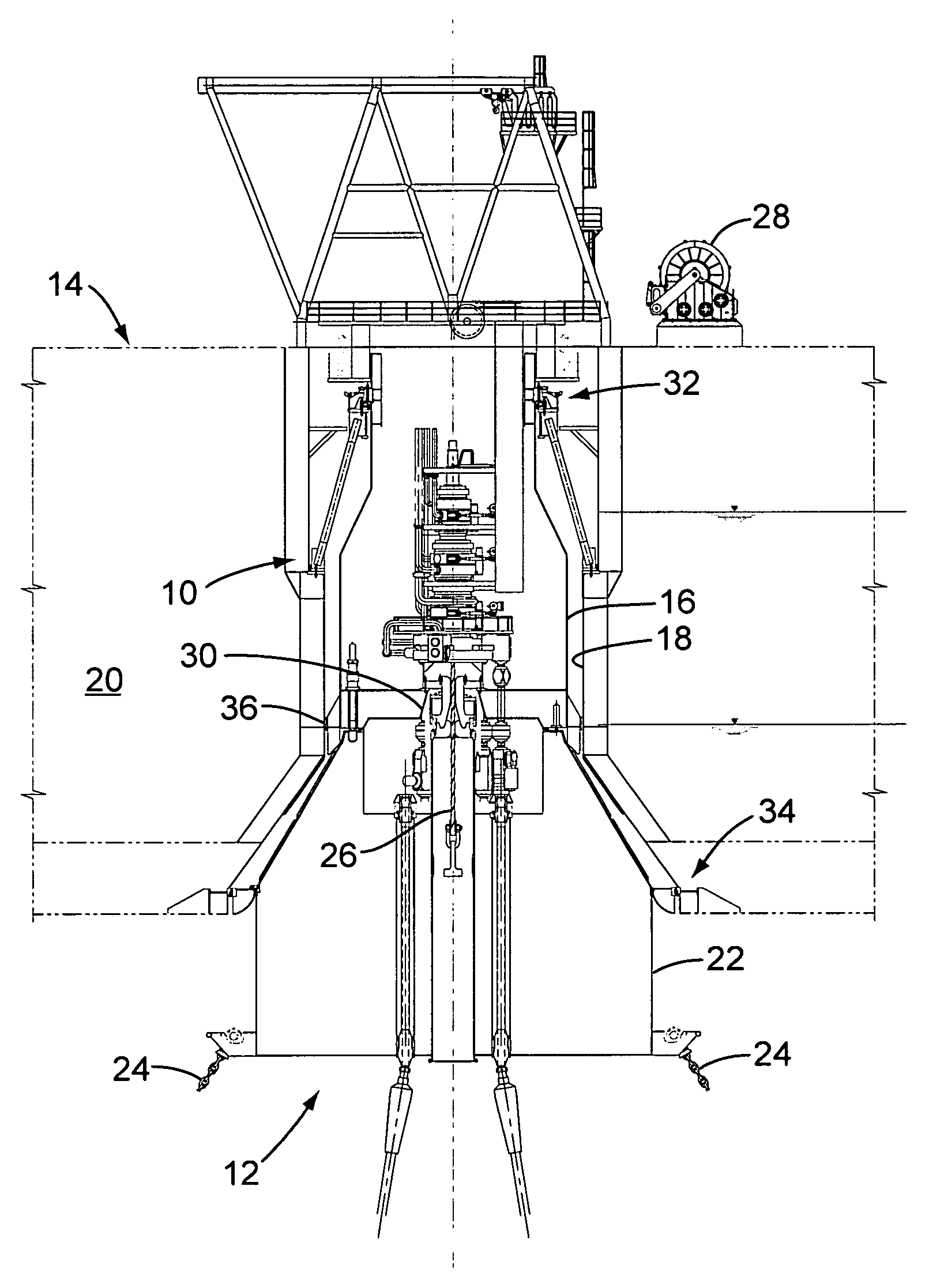
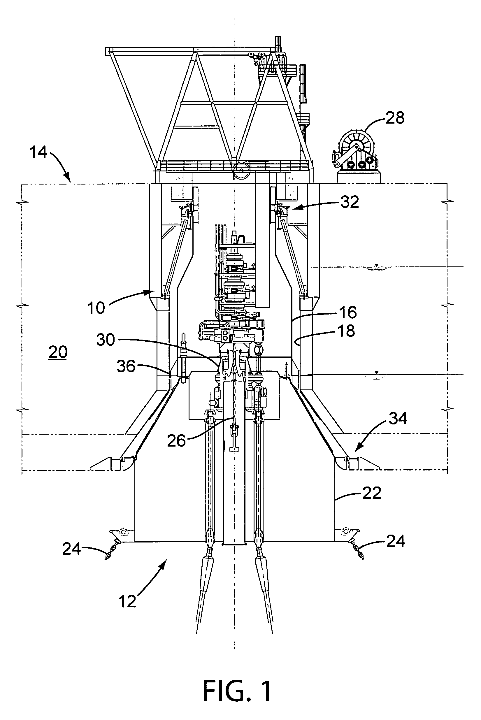
[0011]Referring to FIG. 1, the upper bearing support assembly of the present invention, which is indicated generally by reference number 10, is shown installed in an exemplary turret mooring system 12 for a vessel 14. The turret mooring system 12 comprises a turret 16 which is mounted in a moon pool 18 that is formed in the hull 20 of the vessel 14. The turret 16 may be secured to a disconnectable buoy 22 which in turn is anchored to the sea floor using a number of mooring chains 24. In use, the buoy 22 is hoisted from a submerged position to the turret 16 using a pull-in rope 26 that is attached to a hoist 28, and the buoy is connected to the turret with a conventional structural collet connector 30.

[0012]The turret 16 is rotatably supported in the moon pool 18 by an upper bearing assembly 32 and, when the buoy 22 is attached to the turret, a lower bearing assembly 34. In this manner, the vessel 14 is allowed to weathervane around the turret 16 while still being firmly anchored to ...


PUM


Abstract

A turret mooring system for a vessel which includes a moon pool comprises a turret which is positioned in the moon pool, a buoy and anchor chain assembly for anchoring the turret to the sea floor, a bearing assembly for rotatably connecting the turret to the vessel, and a bearing support assembly which comprises an upper ring member to which the bearing assembly is connected, a lower ring member which is connected to the vessel in the moon pool, and a number of elongated support beams which are connected between the upper and lower ring members. In addition, the lower ring member is connected to the vessel near the vertical center of the vessel in order to minimize the deflections of the bearing assembly due to hogging and sagging of the vessel.

Description

[0001]This application is based on U.S. Provisional Patent Application No. 60 / 465,092, which was filed on Apr. 23, 2003.BACKGROUND OF THE INVENTION[0002]The present invention is directed to a turret mooring system which comprises a turret that is rotatably supported in the moon pool of a vessel by at least an upper bearing assembly. More particularly, the invention is directed to a bearing support assembly which isolates the upper bearing assembly from deflections of the vessel.[0003]Turret mooring systems are commonly used to anchor a vessel to the sea floor. Internal turret mooring systems typically comprise a turret which is rotatably supported in a moon pool that is formed in the hull of the vessel between the bow and the stern. The turret is often supported by both an upper bearing assembly which is connected between the upper end of the turret and the top of the moon pool and a lower bearing assembly which is connected between the lower end of the turret and the bottom of the ...

Claims


Application Information

Patent Timeline
IPC IPC(8): B63B21/00B63B21/50B63B22/02
CPCB63B21/508B63B22/026B63B22/023
Inventor LINDBLADE, STEPHEN P.DANG, QUOC A.
Owner SOFEC
Why Eureka
Try Eureka