
Storage battery temperature regulator having thermoelectric transducer, and vehicle including the storage battery temperature regulator

a technology of temperature regulator and storage battery, which is applied in the field of temperature regulator, can solve the problems of shortening the battery needs a long time for recovery, and shortening the expected service life of the battery

Inactive Publication Date: 2006-06-13
PANASONIC CORP
View PDF16 Cites 66 Cited by
  • Summary
  • Abstract
  • Description
  • Claims
  • Application Information

AI Technical Summary

Benefits of technology

"The patent describes a device that regulates the temperature of a battery using a special material called a thermoelectric transducer. This transducer can both absorb and dissipate heat, depending on how it is stimulated. One side of the transducer is in contact with the battery, while the other side is in contact with a substance that helps speed up the heat transfer. The device helps to maintain the battery at a safe temperature."

Problems solved by technology

However, self-heating of the battery shortens its expected service-life.
When a temperature rises, dilute sulfuric acid gas runs away, which erodes the electrodes, so that the service life of the battery is shortened.
However, those discharge restricting methods discussed above force the users to use the battery only for a short period due to the temperature rise of the battery, and the battery needs a long time for recovery.
Thus a hybrid car employing one of those methods cannot fully enjoy the advantages of the hybrid.
On the other hand, the nickel metal hydride battery and the lithium-ion battery cannot work properly at a low temperature, thus they need to be warmed up.
However, conventional temperature regulating techniques for warming up cannot deal with severe low temperatures in cold areas.

Method used


Image

  • Storage battery temperature regulator having thermoelectric transducer, and vehicle including the storage battery temperature regulator
  • Storage battery temperature regulator having thermoelectric transducer, and vehicle including the storage battery temperature regulator
  • Storage battery temperature regulator having thermoelectric transducer, and vehicle including the storage battery temperature regulator

Examples


exemplary embodiment 1

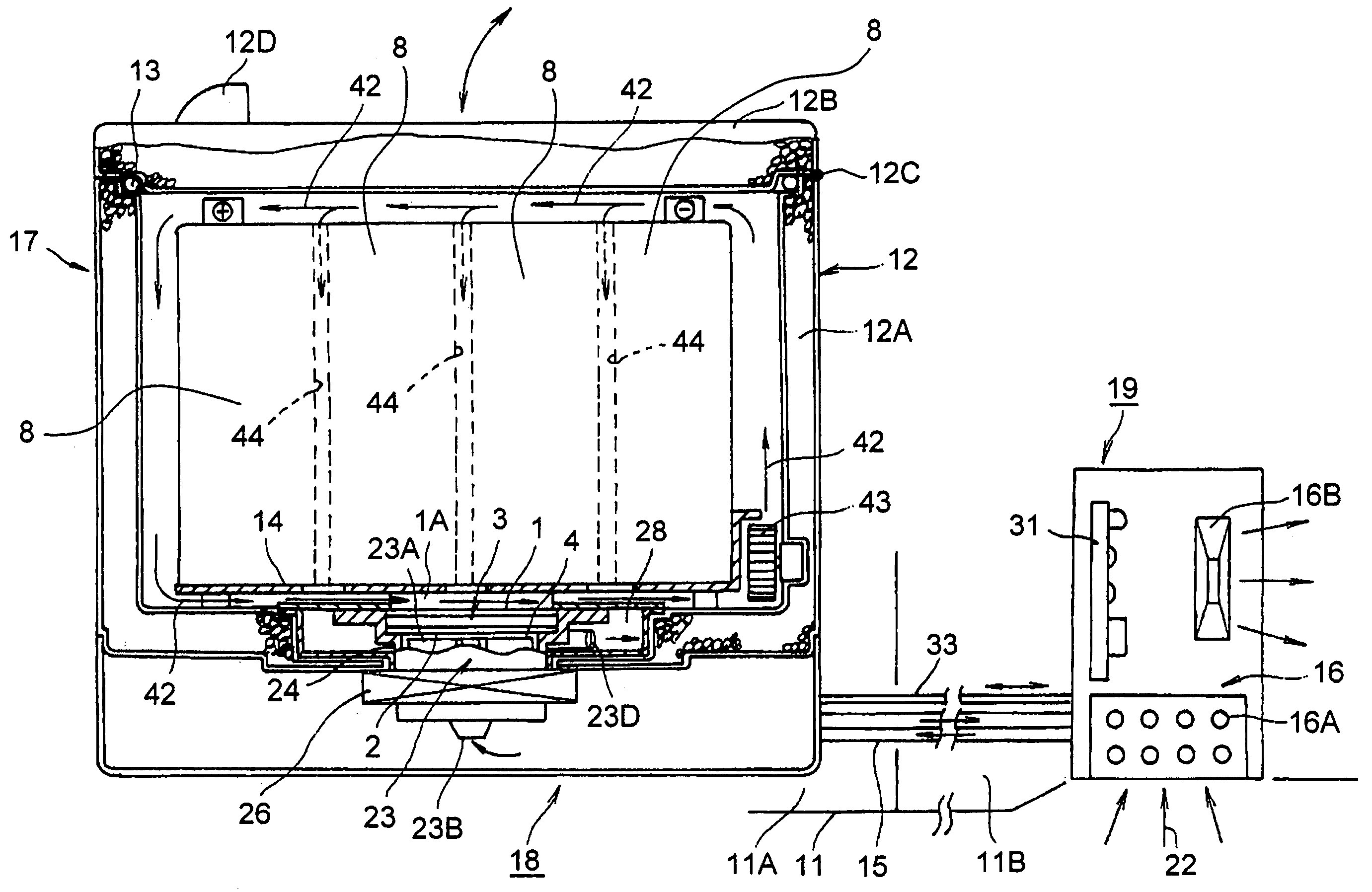
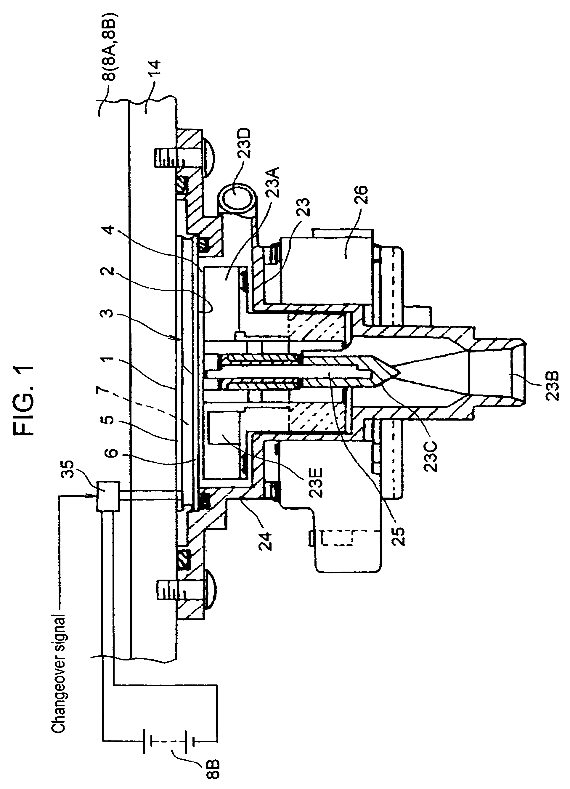
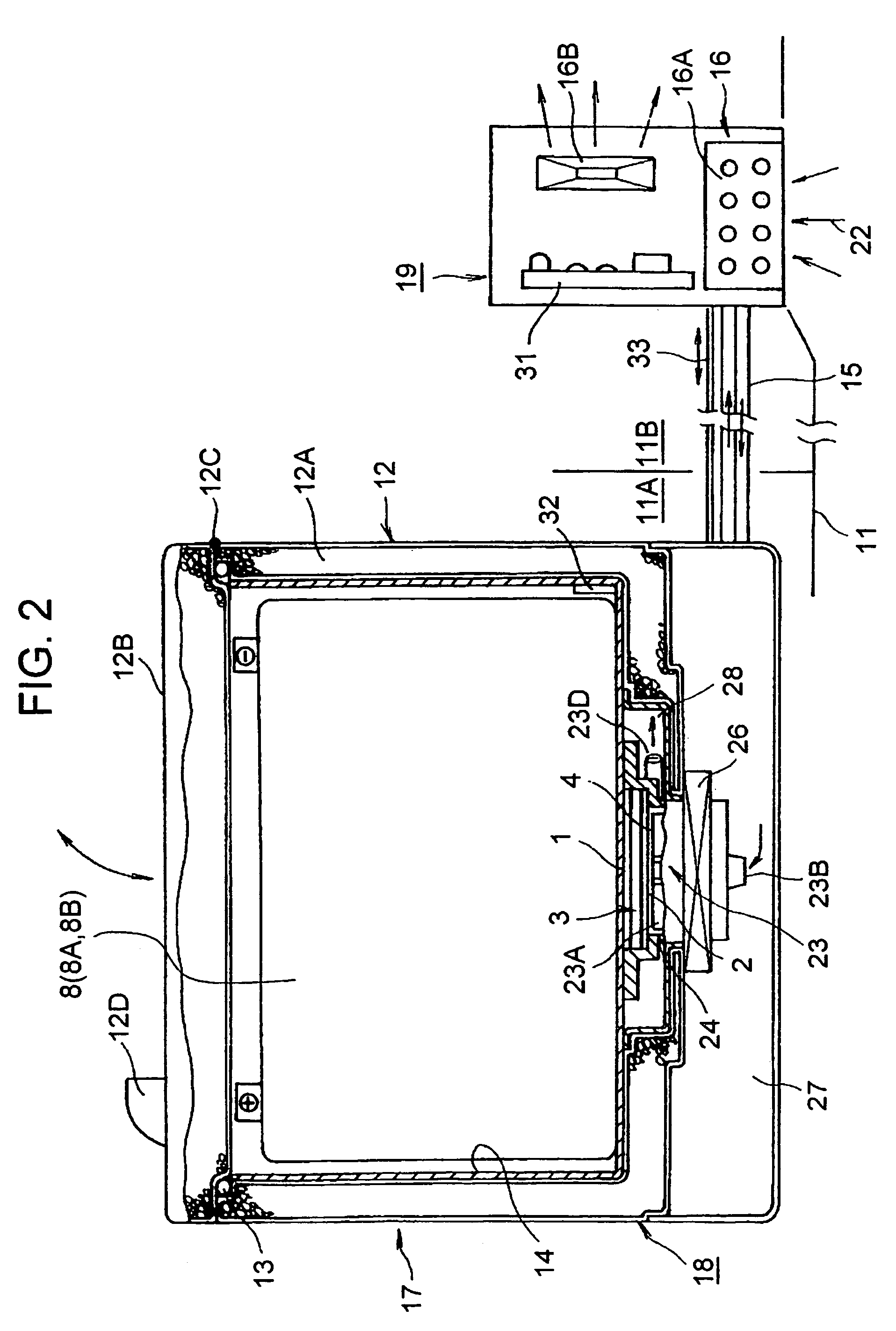
[0022]A temperature regulator of a storage battery in accordance with the first embodiment includes thermoelectric transducer 3 that does two jobs contradictory to each other, i.e., dissipating and absorbing heat using its first face 1 and second face 2. In this first embodiment, thermoelectric module 7 is used in thermoelectric transducer 3, and employs a Peltier element. In the Peltier element, P-type semiconductors and N-type semiconductors are thermally arranged in parallel, but electrically connected in series. When a current runs through the Peltier element, heat-absorption and heat-dissipation occur on the respective faces due to the Peltier effect. This Peltier element is disposed between heat-transferring and insulating plates 5, 6 made of ceramic, and then those elements are sealed and integrated by encapsulating material made of resin. Heat-transferring plates 5 and 6 form first face 1 and second face 2 of thermoelectric module 7.

[0023]In order to regulate a temperature o...

exemplary embodiment 2

[0041]In the second embodiment illustrated in FIG. 4, main unit 18 and sub unit 19 similar to those in the first embodiment illustrated in FIG. 1 through FIG. 3 are placed in trunk 11B of car 11 at an inner right-end and an inner left-end respectively. These places hardly block baggage from being loaded. Since sub unit 19 is placed near to a side face of the car body, the intake port and discharge port are provided on the side face of car 11. Thus ambient air is taken into temperature regulating section 16 and supplied to heat exchanger 16A for exchanging heat. This structure allows temperature regulating section 16 to use fresh ambient air and increase a regulating efficiency compared with a case where the air in trunk 11B is repeatedly used.

exemplary embodiment 3

[0042]In the third embodiment illustrated in FIG. 5 and FIG. 6, storage battery compartment 17, where storage batteries 8 are placed, thermoelectric transducer 3 and temperature regulating section 16 are integrated into one unit, namely, temperature regulating unit 41. This structure does not permit the distributed placement discussed in the previous embodiments; however, it advantageously saves circular path 15 and wiring 33 which connect between the units, because all elements are integrated into one unit. In addition, parts of the same wall can be utilized for dual purposes, which lowers the cost. This structure is particularly suitable for a car having a dead space that can accommodate unit 41. In FIG. 6, temperature regulating unit 41 is mounted in trunk 11B; however, it can be mounted in cabin 11A.


PUM

PropertyMeasurementUnit
operating temperatureaaaaaaaaaa
temperatureaaaaaaaaaa

Abstract

A temperature regulator efficiently regulates a temperature of a storage battery. The regulator includes a thermoelectric transducer having a first face and a second face. The first face is thermally coupled with one or plural storage batteries, and the second face is thermally coupled with a thermal action accelerating medium that accelerates thermal action on the second face. The first face and the second face do two jobs contradictory to each other, i.e., heat dissipation and heat absorption, responsive to a polarity in exciting the battery. This structure allows the temperature regulator to cool down and warm up the storage battery.

Description

TECHNICAL FIELD[0001]The present invention relates to a temperature regulator of a storage battery and a vehicle including the same temperature regulator. More particularly it relates to a temperature regulator of a storage battery suitable for vehicles such as an electric car and a hybrid car, and also relates to a vehicle including the same temperature regulator.BACKGROUND ART[0002]Electric cars and hybrid cars have been commercialized, in which a drive-motor and a storage battery for driving the drive-motor are mounted to those cars. The hybrid car, in particular, fits modern life and draws market attention.[0003]FIG. 8 shows a driving system of a hybrid car available in the market. An engine, a drive-generator and an air-conditioning compressor are mounted in the car. The engine drives both of the compressor and drive-wheels. A control system includes a control unit (ECU), a DC / DC converter and an inverter. A storage battery of 36V is mounted for driving the drive-generator, and...

Claims


Application Information

Patent Timeline
Patent Type & Authority Patents(United States)
IPC IPC(8): H01M10/46B60K1/04B60H1/22B60K6/20B60K6/28B60L50/16G05D23/19H01L35/28H01M10/48H01M10/60H01M10/625H01M10/6572
CPCG05D23/1919H01M10/486H01M10/5004H01M10/5006H01M10/5095H01M10/5067H01M10/5073H01M10/5085H01M10/5087H01M10/5016H01M10/625H01M10/615H01M10/663H01M10/6563H01M10/6572H01M10/6566H01M10/613H01M10/658B60L1/003B60L2210/10B60L2210/40B60L2240/34B60L2240/545B60L2270/44Y02T10/70B60L50/16B60L58/20B60L58/26B60L58/27B60L50/66B60L50/64Y02T10/72Y02T10/7072Y02E60/10
Inventor NISHIHATA, HIDEOKIDO, OSAO
Owner PANASONIC CORP
Learn More