
Device for delivering a sensor to the endovascular system and method of use

a sensor and endovascular technology, applied in the field of devices for introducing sensors into the endovascular system, can solve problems such as health risk, gradual vessel expansion, blood clots or internal bleeding,

Active Publication Date: 2006-06-13
MEDTRONIC VASCULAR INC
View PDF11 Cites 81 Cited by
  • Summary
  • Abstract
  • Description
  • Claims
  • Application Information

AI Technical Summary

Benefits of technology

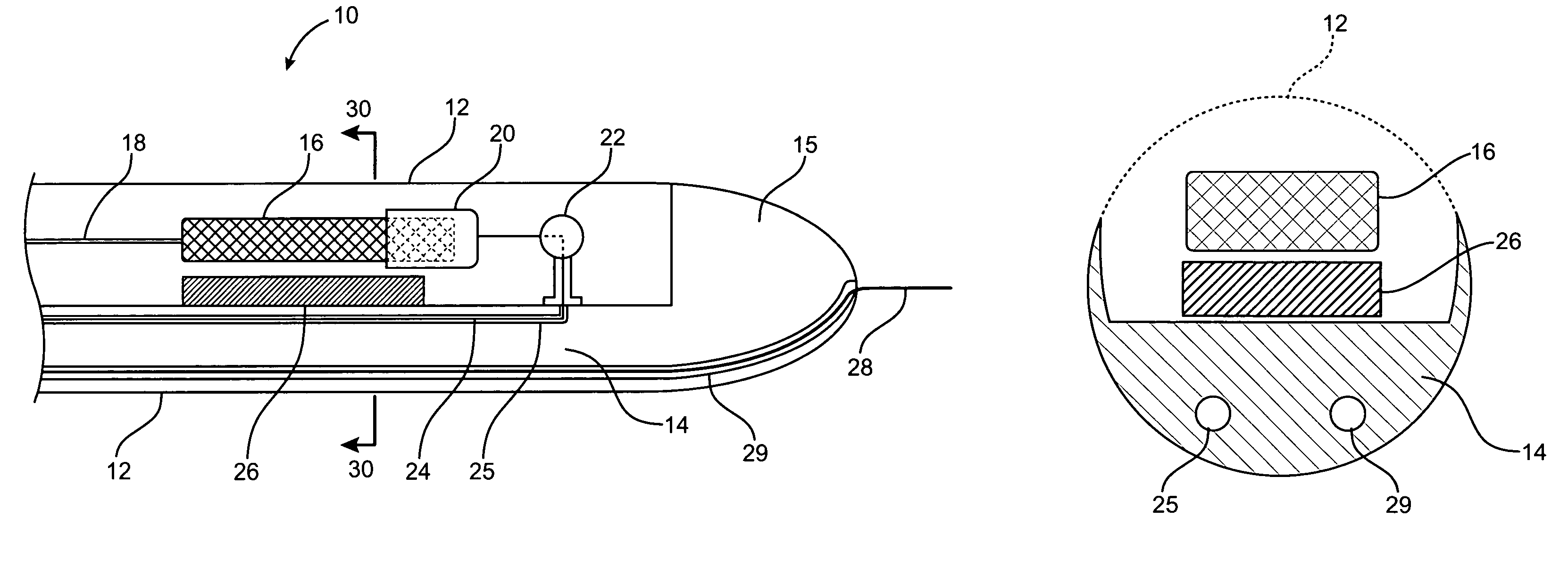
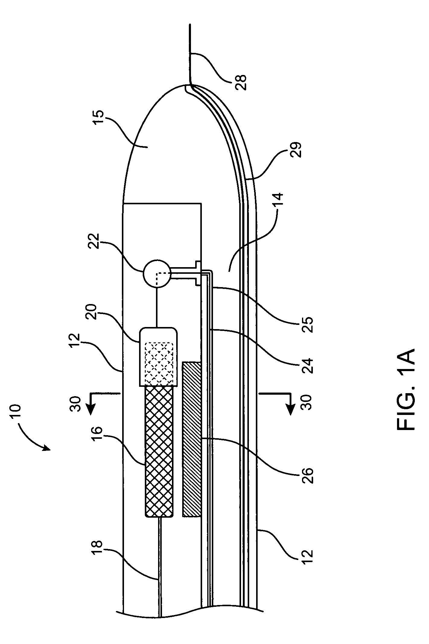
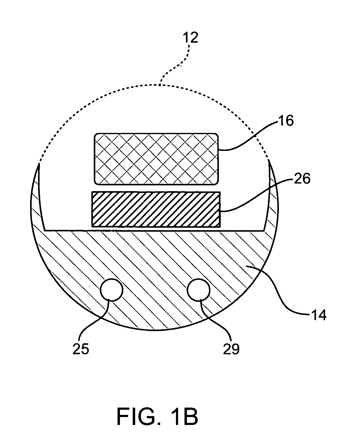
[0016]Another aspect according to the invention provides a delivery system for a sensor with a lead that comprises a catheter with a peelable sheath, and a biasing member, in which both the sheath and biasing member are attached to the catheter. The sheath is perforated along its entire length. The biasing member comprises an expandable balloon positioned within the sheath,

Problems solved by technology

Vascular aneurysms are produced when a thinning or weak spot in a vessel wall dilates, eventually posing a health risk from its potential to rupture, dissect, cause blood clots, or internal bleeding.
Left untreated, aneurysms may lead to gradual vessel expansion, thrombus formation leading to stroke or other vessel blockage, vessel rupture, shock, and eventual death.
However, the surgical procedure is complex and requires experienced surgeons and well equipped surgical facilities.
Patients suffering from such aneurysms are often elderly and weakened from cardiovascular and other diseases.
Furthermore, conventional aneurysm repair has a relatively high mortality rate, usually from 2 to 10%.
Even with successful surgery, recovery takes several weeks and often requires a lengthy hospital stay.
As a result, the fluid seal may be compromised and blood may leak into the aneurysm from the aorta thereby elevating the aneurysmal pressure.
In rare situations, the patient may suffer from anaphylactic responses involving mental confusion, dizziness (due to a drop in blood pressure), swelling (especially of the face, tongue and throat), and difficulty breathing.
The reactions can be serious if not treated immediately.
However, such methods may not effectively detect the presence of an endoleak.
For example, if the aneurysm is largely filled with a thrombus, a sufficient amount of contrast solution may not be introduced into the aneurysm.
This circumstance may lead to a reduced capacity to detect endoleakage.
Continued undetected endoleakage, even at a low level, may slow or even reverse the aneurysmal healing process.
Although such a device is capable of delivering pressure measurements from within the vasculature, it requires a complex device including a sizable implant in a body cavity.
The sensor is deployed by pushing it from the distal tip of the catheter, a process that may damage the sensor.
This delivery system is clearly designed to deliver tubular or ring-shaped implants, and would not be useful for solid implants.
The above examples disclose highly specialized delivery systems that are not widely applicable for purposes other than those for which they were designed.

Method used


Image

  • Device for delivering a sensor to the endovascular system and method of use
  • Device for delivering a sensor to the endovascular system and method of use
  • Device for delivering a sensor to the endovascular system and method of use

Examples


second embodiment

[0034]FIG. 2 provides a cross sectional side view of the delivery device 40, the invention. This delivery device includes a catheter body 14 with a tapered nose cone 15, and optionally, a lumen 29 to accommodate guide wire 28. A sheath 12 is rotatably attached to the proximal end of the catheter nose cone, and covers the sensor 16 and lead 18. The lead 18 may not be present, if not required for the functioning of the sensor 16. Deployment device 26 may be either a compressible material or an expandable balloon. If deployment device 26 consists of an expandable balloon, it is connected to a lumen 33, the lumen being connected to a reservoir of flowable gel or liquid at the proximal end of the device, as is known in the prior art. If a compressible material is used, it is maintained in its compressed state by the sensor 16 and sheath 12 until the sheath 12 is opened. The sheath 12 includes an oblong opening 32, large enough for the sensor 16 to pass through. As shown in FIG. 2, the sh...

third embodiment

[0036]the present invention is shown in FIG. 4A and FIG. 4B. Delivery device 50 includes a catheter 14 with a tapered or rounded nose cone 15. Proximal to the nose cone 15, is a chamber 36 of a size that can accommodate the sensor 16. The lead 18, if present, is disposed along the exterior of the catheter 14, held in place by any appropriate bioadhesive, for example, a glucose-based bioadhesive, or with a hook at the proximal part of the sensor. Slidably attached to the catheter 14 is a sheath 34, placed so that it covers the chamber 36 when in the closed position (FIG. 4A), and presents a smooth exterior. Attached to the proximal end of the sheath 34 is a wire or lever 38 that provides a means of moving the sheath 34. When the sheath 34 is in the closed position, as in FIG. 4A, the wire or lever 38 may be pushed to move the sheath 34 forward along the catheter toward the nose cone 15, until it is in the open position (FIG. 4B). From the open position, the sheath 34 may be returned ...


PUM


Abstract

A delivery system for delivering a sensor to a body cavity includes a catheter and sheath slidably or rotatably coupled to the catheter. The sheath may be retractable and peelable. The delivery device may include an expandable balloon or a crushable material capable of moving the sensor laterally away from the catheter, to the target site. One embodiment of the delivery system includes a deployment device comprising a cord operably engaged with a pulley, and attached at the distal end to a cap engaged with the sensor. Another embodiment of the delivery system comprises a catheter having a chamber that can accommodate the sensor, and a sheath slidably coupled to the exterior of the catheter, and covering the chamber when the sheath is in the closed position. Further included is a method of delivering a sensor to a body cavity using any of the embodiments of the delivery system.

Description

TECHNICAL FIELD OF THE INVENTION[0001]The present invention relates generally to a device for the introduction of a sensor into a human or animal body, especially into a blood vessel.BACKGROUND OF THE INVENTION[0002]Vascular aneurysms are produced when a thinning or weak spot in a vessel wall dilates, eventually posing a health risk from its potential to rupture, dissect, cause blood clots, or internal bleeding. While aneurysms can occur in any blood vessel, most occur in the aorta and peripheral arteries. The majority of aortic aneurysms occur in the abdominal aorta, usually beginning below the renal arteries and often extending into one or both of the iliac arteries. The etiology of aneurysm formation is not entirely understood, but is thought to be related to congenital thinning of the artery, atherosclerotic vessel degeneration, vessel trauma, infection, smoking, high blood pressure, and other causes leading to vessel degeneration. Left untreated, aneurysms may lead to gradual v...

Claims


Application Information

Patent Timeline
IPC IPC(8): A61B5/00
CPCA61B5/0031A61B5/411A61B5/02014
Inventor LETORT, MICHELRAZE, BRIAN
Owner MEDTRONIC VASCULAR INC
Learn More