
Spoolable composite coiled tubing connector

Inactive Publication Date: 2006-06-13
HALLIBURTON ENERGY SERVICES INC
View PDF30 Cites 27 Cited by
  • Summary
  • Abstract
  • Description
  • Claims
  • Application Information

AI Technical Summary

Benefits of technology

[0040]A further advantage of the present invention is that the connector may be assembled without imparting rotational forces on either length of coiled tubing being connected.
[0041]A further advantage of the present invention is that it provides for a strong, well protected contact between matched pairs of electrical conductors in adjoining lengths of composite tubing. This contact is achieved through matching sets of ring contacts. The ring contact attached to the male end has a spring back located underneath the mating surface of the ring contact. Thus when the male contact ring engages the female contact ring, the spring back firmly engages the contacts.
[0042]Another advantage of the electrical contact achieved through the present connector is the insulation it provides from the surrounding well environment as well as between the neighboring electrical signals from adjacent conductors.
[0043]Another advantage of the connector is that many of the parts in the sub-assembly of the connector are the same for both the male and female pieces of the connector. Thus, there is no need for additional designs, drawings, or inventory. The same part may be used for construction of either the male or female housing.
[0044]A still another advantage of the connector is its preferred dimensions. The connector has an outer diameter which is substantially the same as the diameter of the composite coiled tubing allowing the connector to be spoolable onto a reel and to pass through an injector for the tubing. Further, the connector has a limited length such that the connector can be spooled around a reel with the composite coiled tubing.

Problems solved by technology

Many existing wells include hydrocarbon pay zones which were bypassed during drilling and completion because such bypassed zones were not economical to complete and produce.
Offshore drilling rigs cost approximately $40 million to build and may cost as much as $250,000 a day to lease.
Such costs preclude the use of such expensive rigs to drill and complete these bypassed hydrocarbon pay zones.
Presently, there is no cost effective methods of producing many bypassed zones.
The depth that can be drilled by such a bottom hole assembly is limited.
Buckling is particularly acute in deviated wells where gravity does not assist in pulling the tubing downhole.
As the tubing buckles, the torque and drag created by the contact with the borehole becomes more difficult to overcome and often makes it impractical or impossible to use coiled tubing to reach distant bypassed hydrocarbon zones.
Further, steel coiled tubing often fatigues from cyclic bending early in the drilling process and must be replaced.
It has also been found that coiled tubing may be as expensive to use as a conventional drilling system using jointed steel pipe and a rig.
While prior art coiled tubing handling systems are satisfactory for coiled tubing made of metal such as steel, these systems do not accommodate the relatively long spans or drill string lengths achievable with coiled tubing made of composites.
Such accumulation of bending events can seriously undermine the integrity of steel coiled tubing and pose a threat to personnel and rig operations.
However, composite coiled tubing is largely unaffected by such bending events and can remain in service for a much longer period of time.
Moreover, completed but unproductive wells may be reworked to improve hydrocarbon recovery.
However, these dramatic improvements in drilling operations cannot be realized without handling systems that can efficiently and cost-effectively deploy extended lengths of composite coiled tubing.
Prior art coiled tubing handling systems do not readily accommodate the reel change-outs needed when injecting thousands of feet of coiled tubing downhole.
Because such a procedure is inefficient, there is a need for a coiled tubing handling system that more efficiently changes out successive reels of coiled tubing.
The wear layer may also be a sacrificial layer since it will engage the inner wall of the borehole and will wear as the composite umbilical is tripped into the well.
The transmission of signals through composite coiled tubing does present one problem, however.
Materials that are present in the well environment can be highly corrosive and destructive of electrical conductors.
A common shortcoming of the existing methods for connecting composite coiled tubing is that they do not adequately meet the need for a robust and well insulated electrical connection of the electrical conductors in the joined sets of tubing.

Method used


Image

  • Spoolable composite coiled tubing connector
  • Spoolable composite coiled tubing connector
  • Spoolable composite coiled tubing connector

Examples


Embodiment Construction

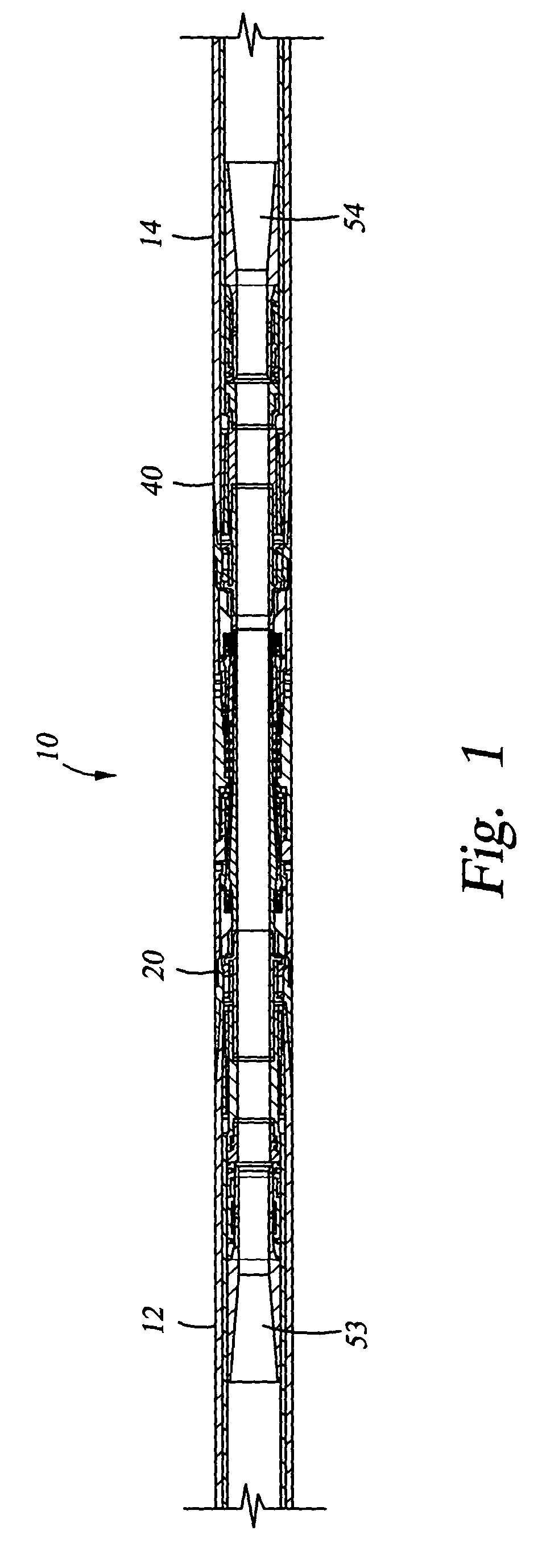
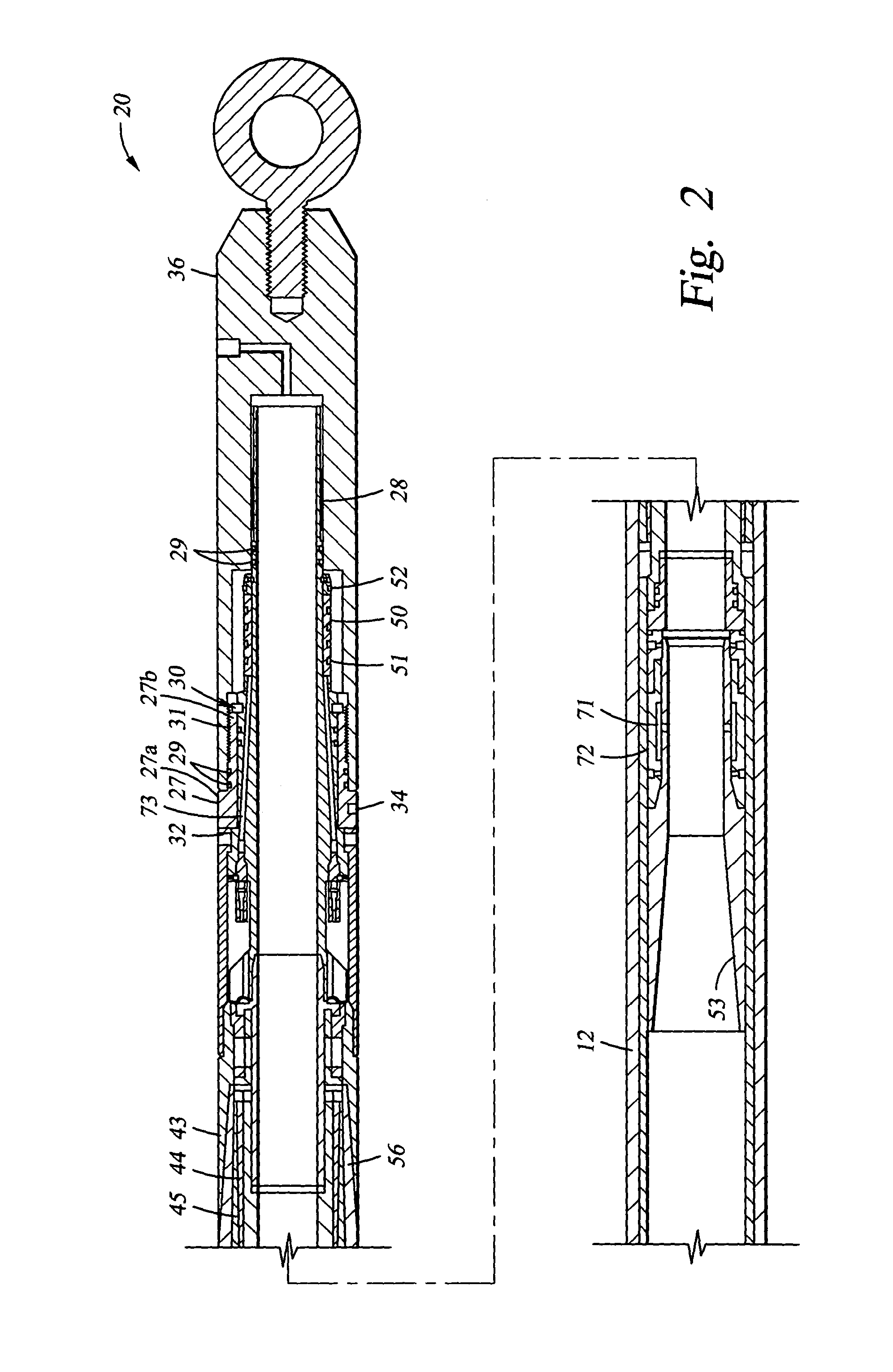
[0035]The preferred embodiments of the connector provide methods and apparatus for connecting two lengths of composite coiled tubing with a connector that can be spooled with the tubing onto a reel and that will pass through an injector. Embodiments of the connector include female and male housings, each of which is connected to a length of composite coiled tubing. The housings are joined together to create the coiled tubing connection and provide mechanical and electrical or fiber optic connectivity between the two lengths of tubing. A connecting member on the male housing includes engages the female housing to connect the two housings. The housings may be aligned by splines on the male housing which align with corresponding flutes on the female housing. The female and male housings are each attached to end portions of the lengths of composite coiled tubing by a clamped connection. The connector has a length which allows it to be spoolable onto a reel with the composite coiled tubi...


PUM


Abstract

A connector providing methods and apparatus for connecting two lengths of composite coiled tubing whereby the connector can be spooled with the tubing onto a reel. Embodiments of the connector include female and male housings which join together to create the coiled tubing connection providing mechanical and electrical or fiber optic connectivity between the two lengths of tubing. A connecting member on the male housing connectably engages the female housing. Splines on the male housing also align with corresponding flutes on the female housing. The female and male housings each attach to end portions of coiled tubing through a clamped connection and with the housings and connecting member being substantially flush with the outside diameter of the coiled tubing.

Description

CROSS-REFERENCE TO RELATED APPLICATIONS[0001]The present application is a continuation-in-part application of U.S. application Ser. No. 09 / 534,685, filed Mar. 24, 2000 now U.S. Pat. No. 6,761,574 and entitled Coiled Tubing Connector, which is a divisional and continuation-in-part of U.S. patent application Ser. No. 09 / 081,961 filed May 20, 1998 now U.S. Pat. No. 6,296,066 and entitled Drilling System, which claims the benefit under 35 U.S.C. 119(e) of U.S. Provisional Application Ser. No. 60 / 063,326, filed Oct. 27, 1997 and entitled Drilling System, all of these applications being hereby incorporated herein by reference.STATEMENT REGARDING FEDERALLY SPONSORED RESEARCH OR DEVELOPMENT[0002]Not Applicable.FIELD OF THE INVENTION[0003]The present invention relates generally to devices used to connect lengths of coiled tubing and more particularly to devices used to connect lengths of composite coiled tubing. Another feature of the present invention relates to providing a mechanical conne...

Claims


Application Information

Patent Timeline
IPC IPC(8): H01R4/60E21B4/18E21B7/06E21B17/02E21B17/03E21B17/042E21B17/046E21B17/20E21B19/07E21B19/086E21B19/16E21B21/10E21B23/00E21B29/06E21B37/00E21B47/01E21B49/08G01V3/30
CPCE21B4/18G01V3/30E21B17/02E21B17/028E21B17/03E21B17/042E21B17/046E21B17/206E21B19/07E21B19/086E21B19/161E21B21/103E21B29/06E21B37/00E21B47/01E21B7/068E21B2023/008E21B23/001
Inventor SONG, HAOSHIESTEP, JAMES W.
Owner HALLIBURTON ENERGY SERVICES INC
Learn More