
Apparatus and method of shipping and installation of ATM

a technology of automatic teller machine and atm, which is applied in the direction of metal working apparatus, transportation and packaging, packaging, etc., can solve the problems of machine damage, manpower and time, and high cost of equipment, and achieve the effect of reducing the time, material and equipment needed to install an atm on a pallet, and substantially reducing the cos

Active Publication Date: 2009-07-07
DIEBOLD SELF SERVICE SYST DIV OF DIEBOLD NIXDORF INC
View PDF19 Cites 21 Cited by
  • Summary
  • Abstract
  • Description
  • Claims
  • Application Information

AI Technical Summary

Benefits of technology

[0004]It is an object of an exemplary form of the present invention to provide a shipping and installation apparatus and method which provides improved protection of ATMs during shipment, and also provides for more rapid, inexpensive, and safe installation of ATMs.
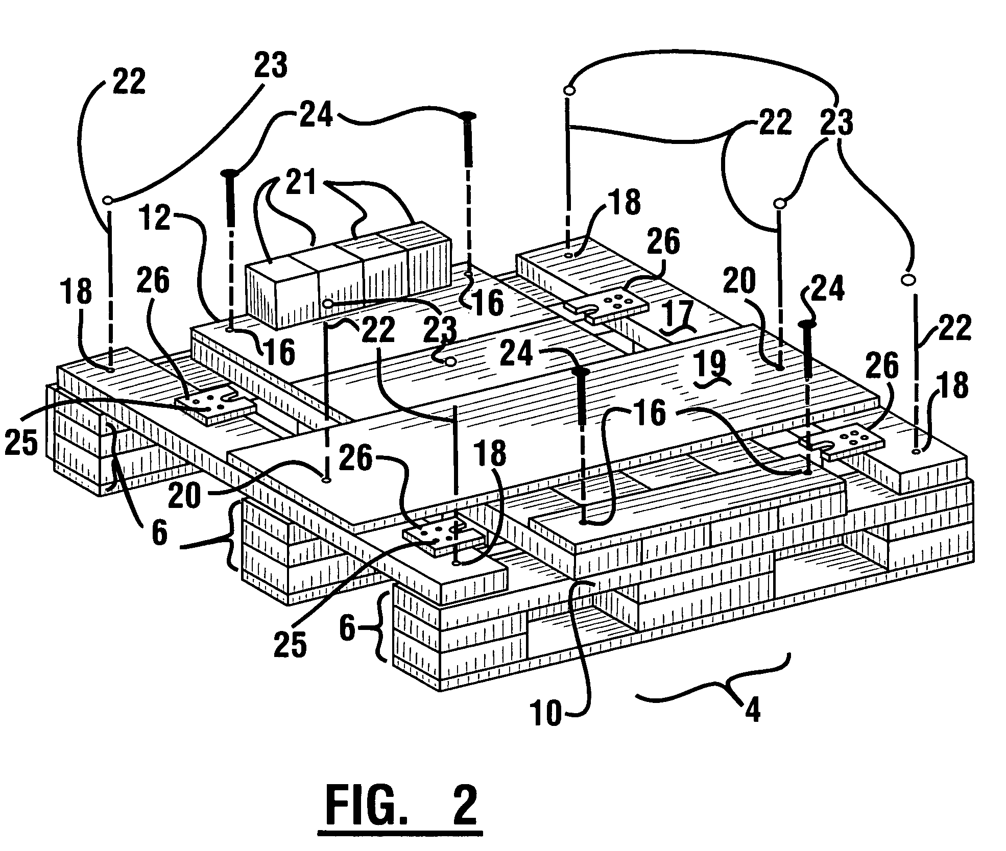
[0008]In operation, the plurality of pallet components of an exemplary embodiment are held in an assembled condition with a plurality of component fasteners. The ATM is secured to the pallet, aligning the plurality of vertical adjustment and support devices with predetermined pallet openings to enable vertical movement of the devices in the openings. In an exemplary embodiment the vertical adjustment and support devices may be moved to firmly engage bracket portions of the pallet to help secure the ATM and pallet in engagement.
[0010]In this exemplary manner, the time, material and equipment needed to install an ATM shipped on a pallet is substantially reduced. While the installation of an ATM using traditional methods often involves hours of labor, risk of damage, and expensive lifting equipment, the use of this exemplary apparatus and method may allow one worker to remove the pallet material and move the ATM to its final operating position in approximately ten minutes using only hand tools.

Problems solved by technology

During shipping, machines occasionally incur damage due to the combination of external impact loads and the relative rigidity of most shipping pallets.
Furthermore, when an ATM arrives at its final destination and requires installation, the machine must be lifted off the pallet for installation.
This lifting often requires expensive equipment, manpower and time, and may pose a risk of damage to the machine or personnel involved.

Method used


Image

  • Apparatus and method of shipping and installation of ATM
  • Apparatus and method of shipping and installation of ATM
  • Apparatus and method of shipping and installation of ATM

Examples


Embodiment Construction

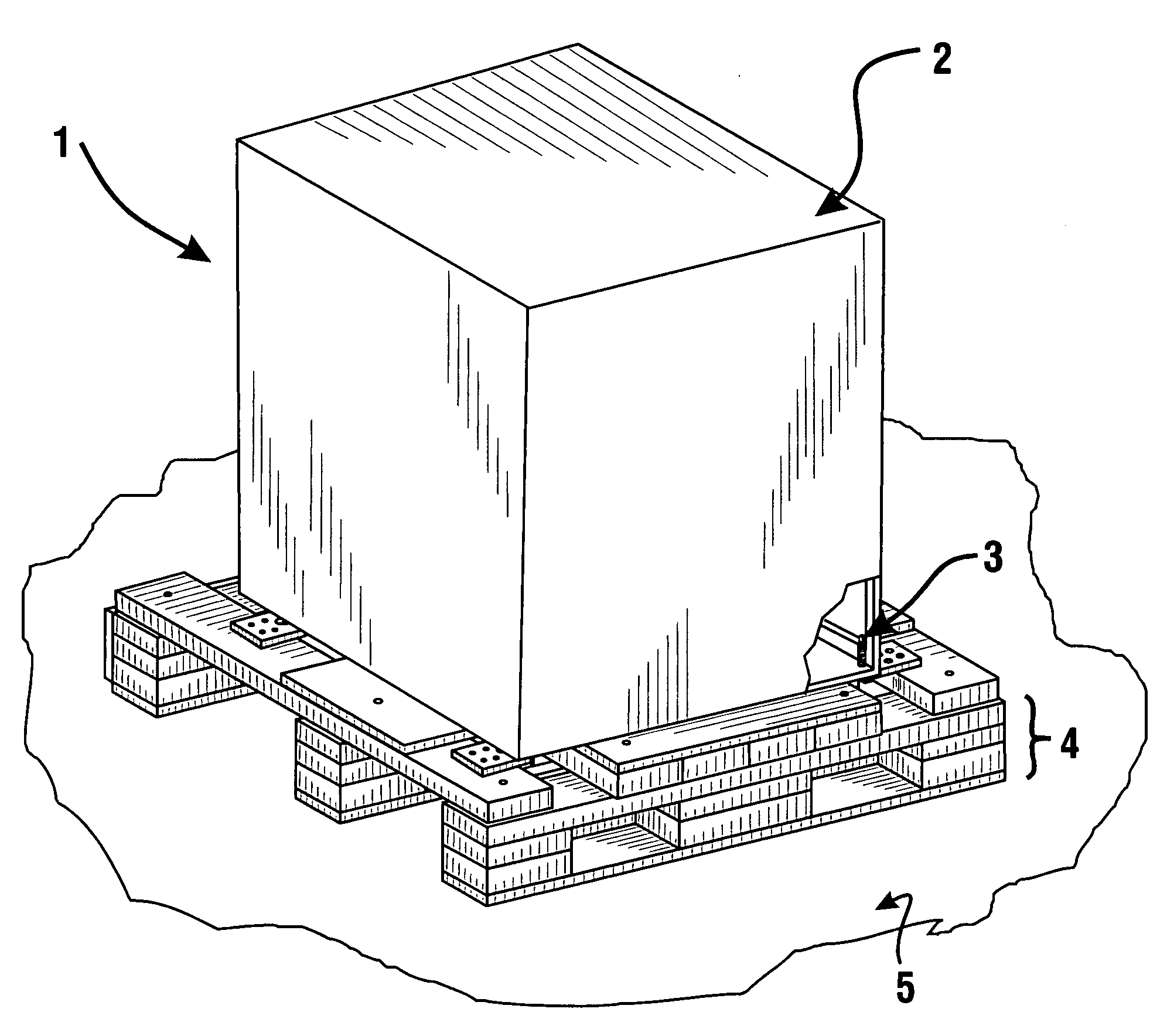
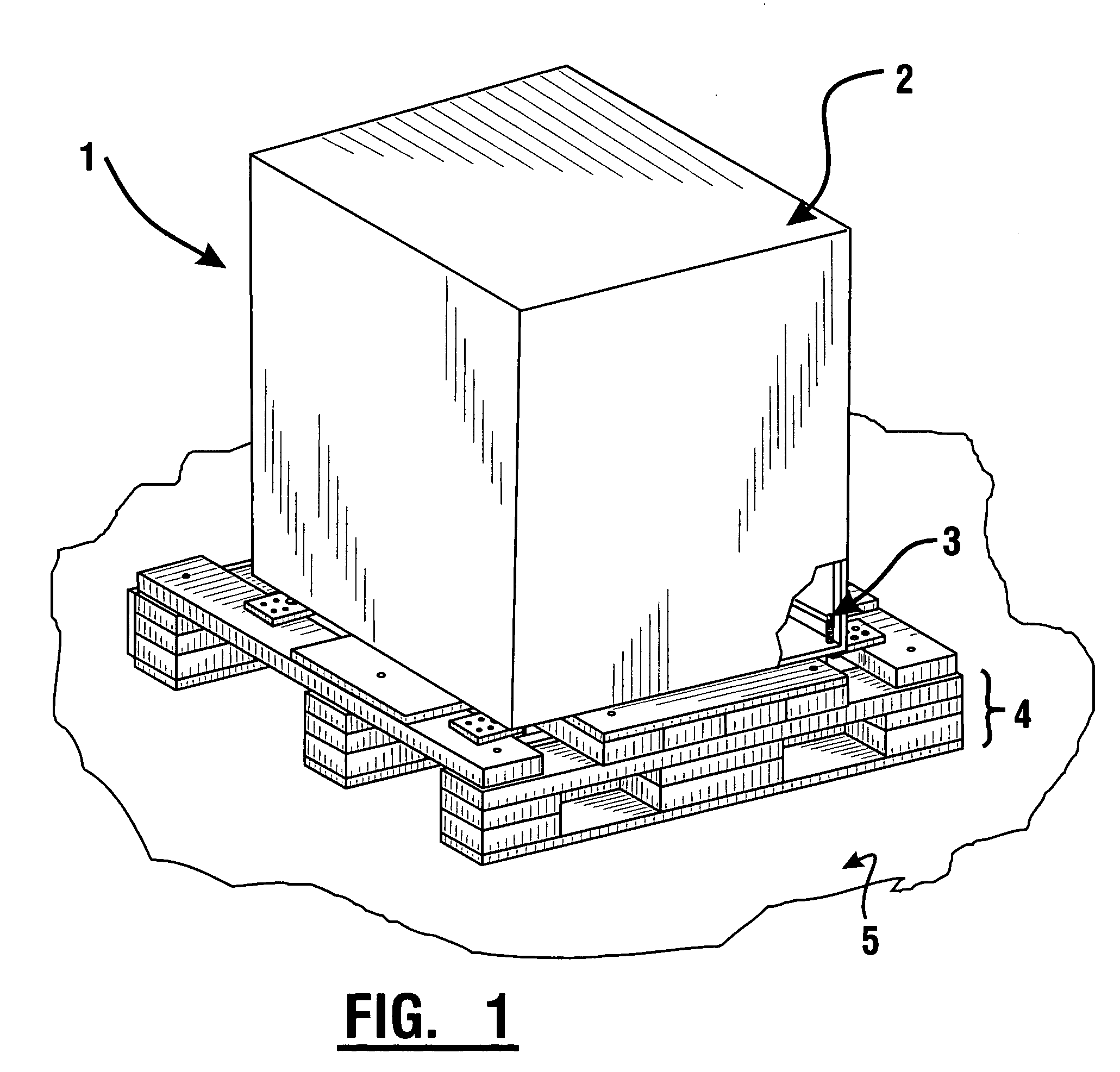
[0019]Referring now to the drawings and particularly to FIG. 1, there is shown therein a perspective view of an exemplary ATM shipping and installation apparatus 1. The ATM shipping and installation apparatus may include a cash dispensing ATM 2. The ATM has a plurality of vertically movable support legs which serve as an exemplary form of vertical adjustment and support devices 3. As shown, a pallet 4 supports the ATM. The pallet is supported on a floor surface 5. The ATM further comprises a base portion 29 discussed later in connection with FIG. 6. The ATM may be one of the types shown in U.S. Pat. No. 6,010,065, the disclosure of which is incorporated herein by reference. In alternative embodiments the ATM could be of another type and may be supported by a differently configured pallet or shipping dunnage mechanism. Similarly, the pallet 4 is exemplary, and a number of other shipping dunnage mechanisms may be used in other embodiments.

[0020]The exemplary pallet 4 is comprised of a...


PUM


Abstract

An apparatus and method for the shipping and installation of an ATM. The ATM comprises leveling legs. A pallet includes a plurality of readily separable components and a plurality of component fasteners. The pallet further comprises bracket openings which align with the leveling legs allowing vertical movement of the leveling legs therethrough. The leveling legs are extendable in the openings to lift and support the ATM from an underlying floor surface, allowing the underlying pallet to be disassembled. The ATM can be leveled using the leveling legs.

Description

CROSS REFERENCE TO RELATED APPLICATION[0001]This application claims benefit pursuant to 35 U.S.C. § 119(e) of U.S. Provisional Application Ser. No. 60 / 534,529 filed Jan. 5, 2004.TECHNICAL FIELD[0002]This invention relates to the shipping and installation of an Automated Teller Machine (ATM). Specifically this invention relates to apparatus and methods which provide for the reliable transport and more rapid installation of ATMs.BACKGROUND ART[0003]When shipping an ATM, the ATM is frequently secured to a shipping pallet to provide protection, stability, and ease of handling. During shipping, machines occasionally incur damage due to the combination of external impact loads and the relative rigidity of most shipping pallets. Furthermore, when an ATM arrives at its final destination and requires installation, the machine must be lifted off the pallet for installation. This lifting often requires expensive equipment, manpower and time, and may pose a risk of damage to the machine or pers...

Claims


Application Information

Patent Timeline
IPC IPC(8): B65B61/00
CPCB65D19/0095B65D19/44B65D2585/6897B65D2519/00029B65D2519/00064B65D2519/00099B65D2519/00104B65D2519/00273B65D2519/00293B65D2519/00323B65D2519/00333B65D2519/00378B65D2519/00562B65D2519/00572B65D2519/00815
Inventor UTZ, ZACHARYKOVACS, DOUGLAS A.
Owner DIEBOLD SELF SERVICE SYST DIV OF DIEBOLD NIXDORF INC
Learn More