
Method for a cable modem to rapidly switch to a backup CMTS

a technology of backup and modem, applied in the field of digital cable network technology, can solve the problems of cable modem service disruption or service outage, unfavorable service type, and difficult task of providing reliable high-quality voice/video communication over such networks, and achieve the effect of reducing delays and fewer significant disruptions

Inactive Publication Date: 2006-06-06
CISCO TECH INC
View PDF54 Cites 107 Cited by
  • Summary
  • Abstract
  • Description
  • Claims
  • Application Information

AI Technical Summary

Benefits of technology

The present invention provides a redundancy technique in a shared-access computer network to reduce delays caused by equipment failure, software failure, or other network problems. It provides a protection CMTS that can immediately service a cable modem in case of a failure of the working CMTS. The cable modem can preregister with the protection CMTS before the cutover to the protection CMTS, and the registration data includes an IP address for the cable modem. The CMTS is designed or configured to perform routing operations and can store the registration parameters for both the working CMTS and the protection CMTS. The invention helps to provide telephony service with fewer significant disruptions in the cable network.

Problems solved by technology

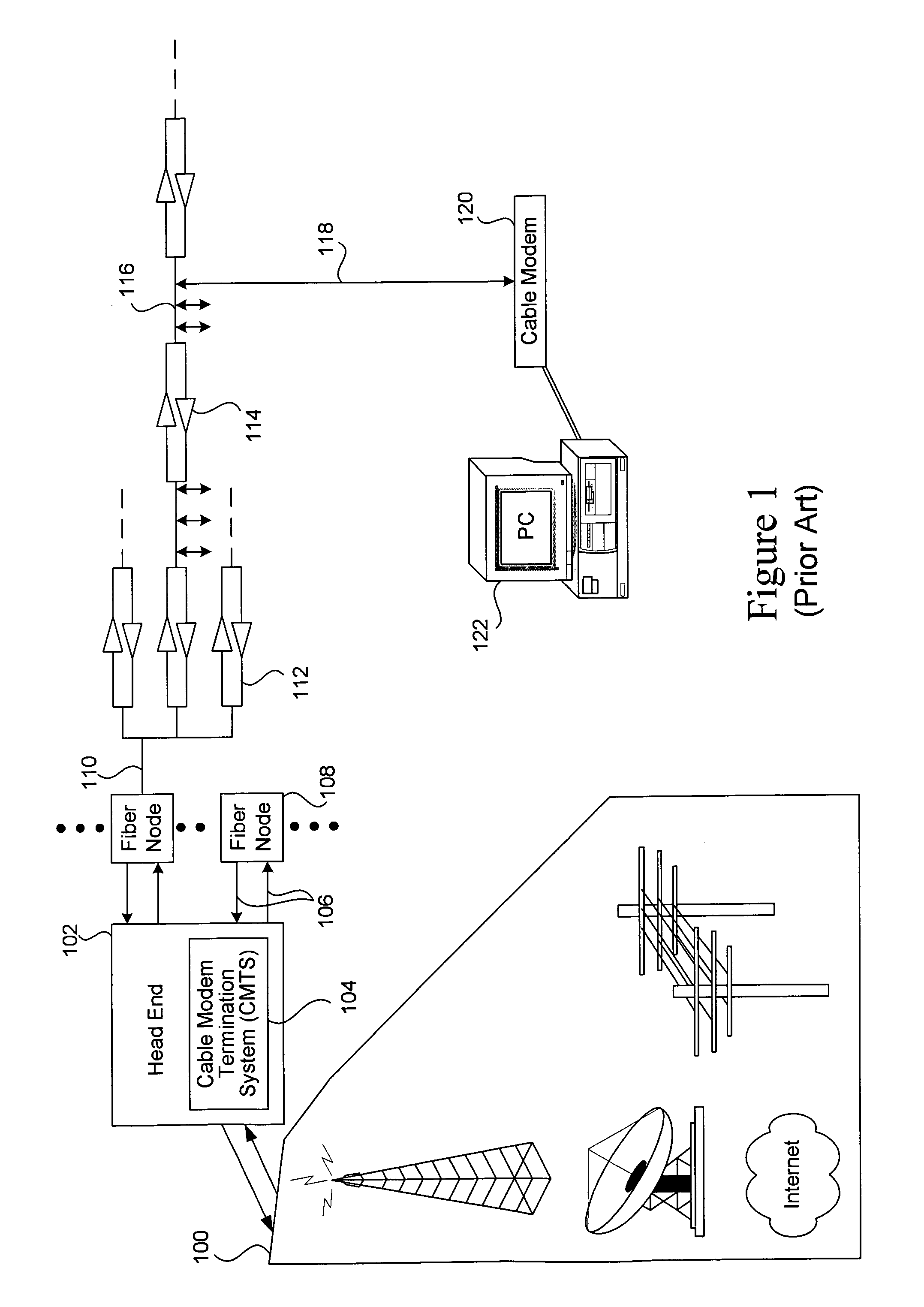
For networks that use a shared access medium to communicate between subscribers and the service provider (e.g., cable networks, wireless networks, etc.), providing reliable high-quality voice / video communication over such networks is not an easy task.
In addition, because cable modems were not used, the head end of pre-HFC cable systems did not contain a CMTS.
Therefore, a failure of the one of the CMTS will result in a service disruption or service outage of the cable modems relying upon the failed element.
If a CMTS fails, for example, it may have to be repaired or replaced before service can resume.
From the perspective of the service provider and the end user, any type of disruption or delay in service is extremely undesirable.
This problem becomes particularly acute as broadband access technologies, including cable, move toward digital telephony (e.g., Voice over IP or “VoIP”).

Method used


Image

  • Method for a cable modem to rapidly switch to a backup CMTS
  • Method for a cable modem to rapidly switch to a backup CMTS
  • Method for a cable modem to rapidly switch to a backup CMTS

Examples


Embodiment Construction

[0032]A. Topologies Examples

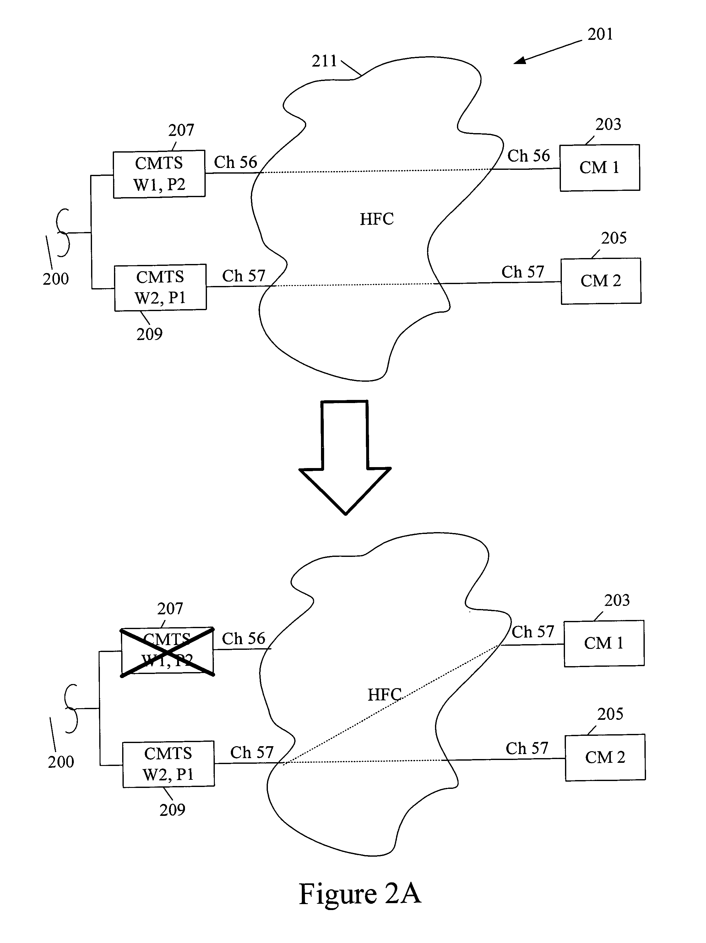
[0033]FIGS. 2A–2E present various cable network topologies that may be used in implementing the present invention. FIG. 2A depicts a network topology deemed “1:1” in which the network includes two CMTSs. Both are working CMTSs and both provide protection for the other. Thus, if one of the two CMTSs fails, the other one assumes the functions of the failed CMTS, while maintaining its own functions.

[0034]As shown in FIG. 2A, a cable network system 201 includes first and second cable modems 203 and 205. Each connects to a separate CMTS. Specifically, modem 203 connects to a CMTS 207 via a downstream channel 56 and modem 205 connects to a CMTS 209 via a downstream channel 57. Each connection is made through an HFC network 211. Communications between the cable modems and external sources are made via a connection 200.

[0035]Note that FIG. 2A is greatly simplified. Normally, a given CMTS or CMTS interface services many cable modems. For example, a single CMTS may...


PUM


Abstract

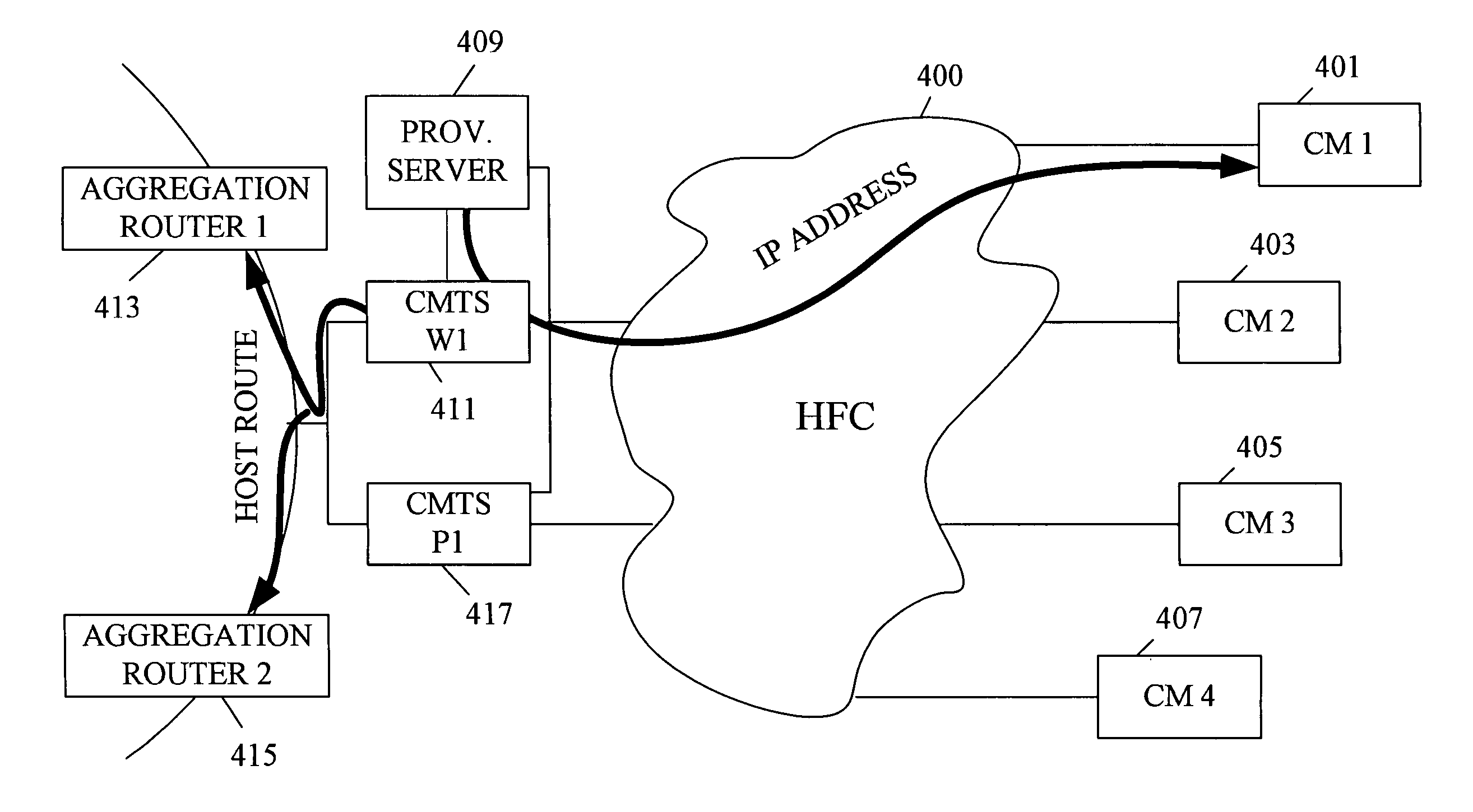
A protection CMTS is available to immediately service a cable modem should that modem's service from a working CMTS fail for any reason. To speed the service transfer (cutover) from the working CMTS to the protection CMTS, the cable modem may preregister with the protection CMTS well before the cutover becomes necessary. The cable modem's registration with both the working CMTS and the protection CMTS preferably employs a single IP address, so that the cable modem need not obtain a new IP address during cutover. While the cable modem may register with both the working CMTS and the protection CMTS, the devices are designed or configured so that only the working CMTS injects a host route for the cable modem into the appropriate routing protocol. Only after cutover to the protection CMTS does the protection CMTS inject its host route.

Description

CROSS-REFERENCE TO RELATED APPLICATION[0001]This invention is related to U.S. patent application Ser. No. 09 / 484,189, filed on the same day as this patent application, naming F. Daruwalla, J. Forster, G. Roeck, R. Woundy, and M. Thomas as inventors, and titled “ROUTING PROTOCOL BASED REDUNDANCY DESIGN FOR SHARED-ACCESS NETWORKS, and U.S. patent application Ser. No. 09 / 484,612, filed on the same day as this patent application, naming Joanna Qun Zang, Feisal Daruwalla, James R. Forster, Guenter E. Roeck, Joseph B. O'Donnell, John Chen and Mark Millet as inventors, and titled “CABLE NETWORK REDUNDANCY ARCHITECTURE.”That application is incorporated herein by reference in its entirety and for all purposes.BACKGROUND OF THE INVENTION[0002]This invention relates to digital cable network technology. More specifically, it relates to methods and apparatus that provide redundancy for critical headend components of digital cable networks.[0003]Broadband access technologies such as cable, fiber ...

Claims


Application Information

Patent Timeline
Patent Type & Authority Patents(United States)
IPC IPC(8): H04L12/26G08C15/00H04J1/16G01R31/08G06F11/00
CPCH04L45/28H04L45/22H04L45/00G06F11/2005
Inventor DARUWALLA, FEISALFORSTER, JAMES R.ROECK, GUENTER E.ZANG, JOANNA QUNLU, YONG
Owner CISCO TECH INC
Learn More