
Hydraulic control circuit for a continuously variable transmission

a technology of hydraulic control circuit and continuously variable transmission, which is applied in the direction of friction gearing, gearing elements, gearing, etc., can solve the problems of rollers not moving with sufficient speed, affecting the transmission function, and imposing particular requirements on the transmission, so as to reduce the degree of opening and rapid ratio change

Inactive Publication Date: 2006-06-06
TOROTRAK (DEV) LTD
View PDF7 Cites 32 Cited by
  • Summary
  • Abstract
  • Description
  • Claims
  • Application Information

AI Technical Summary

Benefits of technology

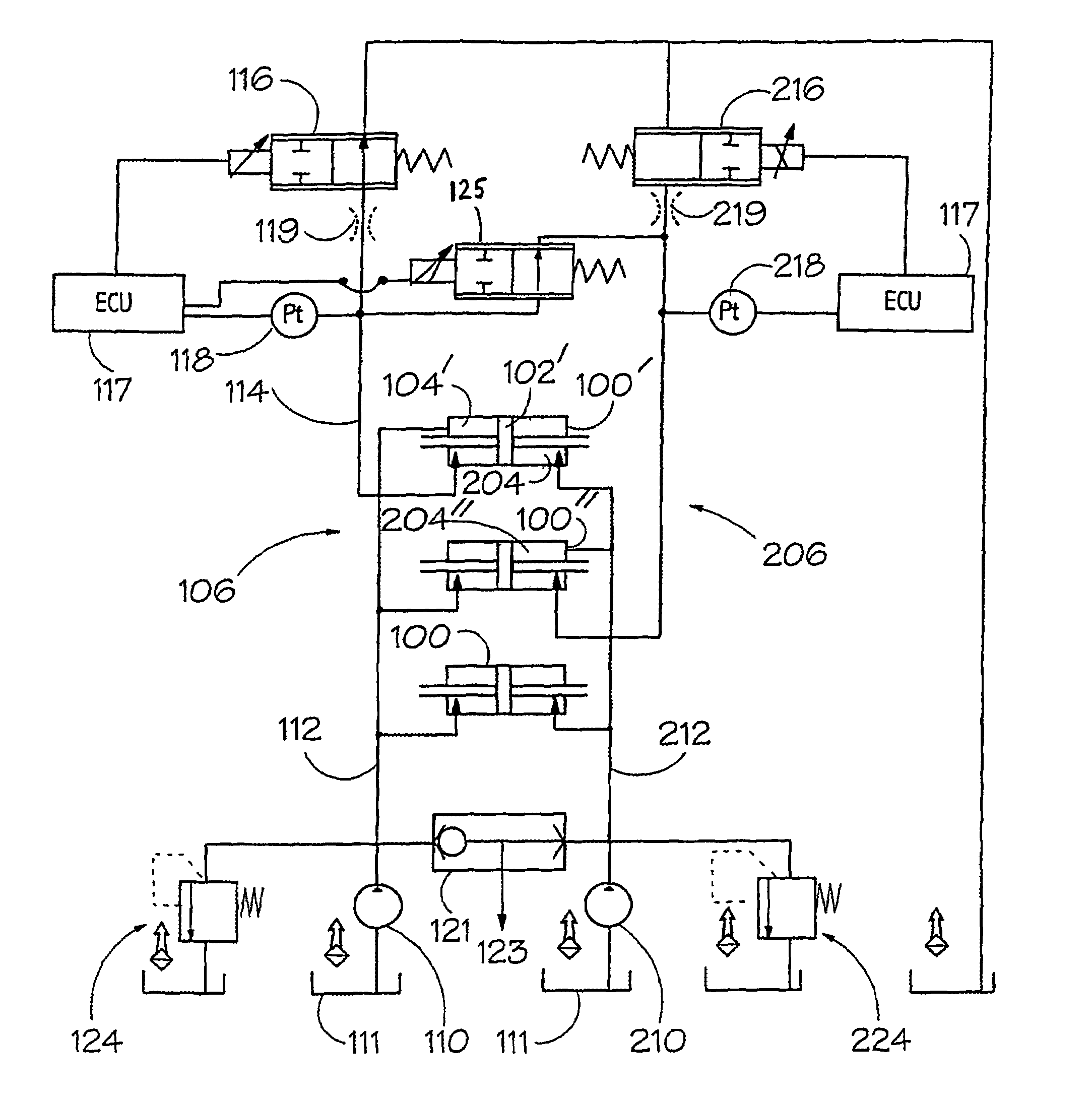
[0012]In accordance with a first aspect of the present invention, there is a hydraulic circuit for a continuously variable transmission comprising a continuously variable ratio unit (“variator”) which is controllable by means of at least one hydraulic actuator acting on a movable torque transmission element of the variator, the actuator having opposed first and second working chambers and the circuit comprising first and second flow lines both connected to respective actuator working chambers for feeding fluid thereto and therefrom and means for supplying fluid flow through both of the flow lines, variable control valve means being incorporated in both flow lines for generating an adjustable back pressure therein and a further valve being connected between the two flow lines, upstream of the variable control valve means, whereby opening of the further valve enables flow of fluid from one flow line to the other in order to reduce pressure difference between the lines.
[0021]It has been found that in this way rapid ratio change may be provided for without an unacceptable degree of oscillation and consequent transmission instability.

Problems solved by technology

It will be appreciated that while the equilibrium position of the rollers is uniquely determined by the balance of the reaction force and the applied biasing force, there is the potential for unwanted oscillatory motion of the roller / carriage combination about this position, with resulting impairment of transmission function.
However, particularly stringent requirements are imposed on the transmission during very rapid changes of vehicle speed, particularly in the case of an emergency rapid “brake to rest” e.g. an emergency stop.
The high rate of ratio change required during a rapid brake to rest corresponds to a rapid motion of the variator rollers, but if adequate hydraulic flow to accommodate such motion is not available—particularly because such flow is restricted—the rollers can fail to move with sufficient speed, leading e.g. to an engine stall.
The result must be a large net biasing force on the roller / carriage combinations and this is reflected in a large variator torque which is the cause of the engine stall.
However the switching valves used in this arrangement provide no control of the resulting flow—control of the variator is effectively lost when the valves are set as just mentioned.
The valves used to normally control hydraulic pressures applied to the variator are rendered ineffective.
This is incompatible with maintenance of stable variator control.

Method used


Image

  • Hydraulic control circuit for a continuously variable transmission
  • Hydraulic control circuit for a continuously variable transmission
  • Hydraulic control circuit for a continuously variable transmission

Examples


Embodiment Construction

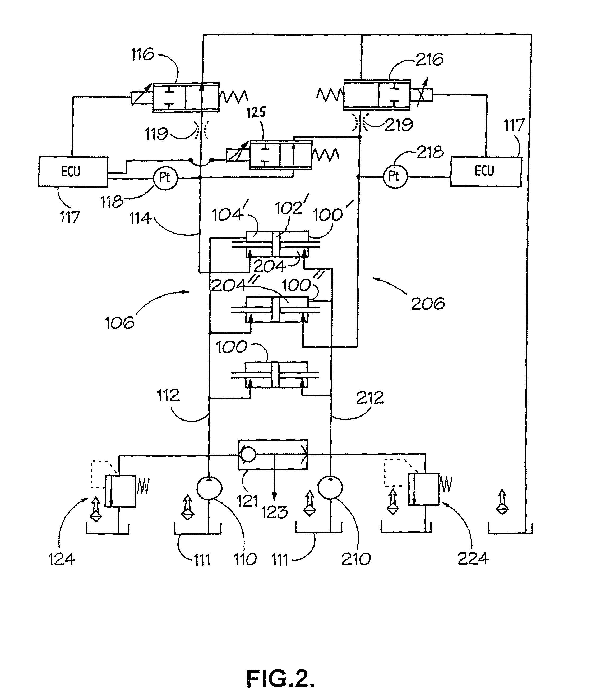
[0026]The hydraulic circuit illustrated in FIG. 2 is suitable for use with a torque control variator of the type described above with reference to FIG. 1. FIG. 2 shows, by way of illustration, a set of three hydraulic actuators 100, 100′ and 100″ (typically in a variator of the above described twin cavity type, six such actuators would be provided—three per cavity—but remaining actuators are omitted for the sake of clarity). Each actuator comprises a piston 102 whose two faces are exposed to control pressure in first and second working chambers 104, 204 so that the biasing force applied by each actuator is determined by the difference in these control pressures. Each actuator 100 is coupled to a corresponding roller / carriage of the type illustrated in FIG. 1.

[0027]The hydraulic circuit provides a first flow line 106 for supplying hydraulic fluid to the first working chambers 104 and a second flow line 206 for supplying fluid to the second working chambers 204. The first flow line 10...


PUM


Abstract

A hydraulic circuit for a continuously variable transmission having a continuously variable ratio unit that is controlled by at least one hydraulic actuator acting on a movable torque transmission element. The actuator has opposed first and second working chambers. The circuit includes first and second flow lines that are connected to two respective actuator working chambers. The lines feed fluid thereto and therefrom A pressurized supply of fluid urges fluid flow through the flow lines. A variable control valve is incorporated in both flow lines. Each valve generates an adjustable back pressure therein. A further valve is connected between the two flow lines. The further valve has a variable opening and is located upstream of the variable control valve. Opening of the further valve enables flow fluid from one flow line to the other to reduce pressure difference between the lines.

Description

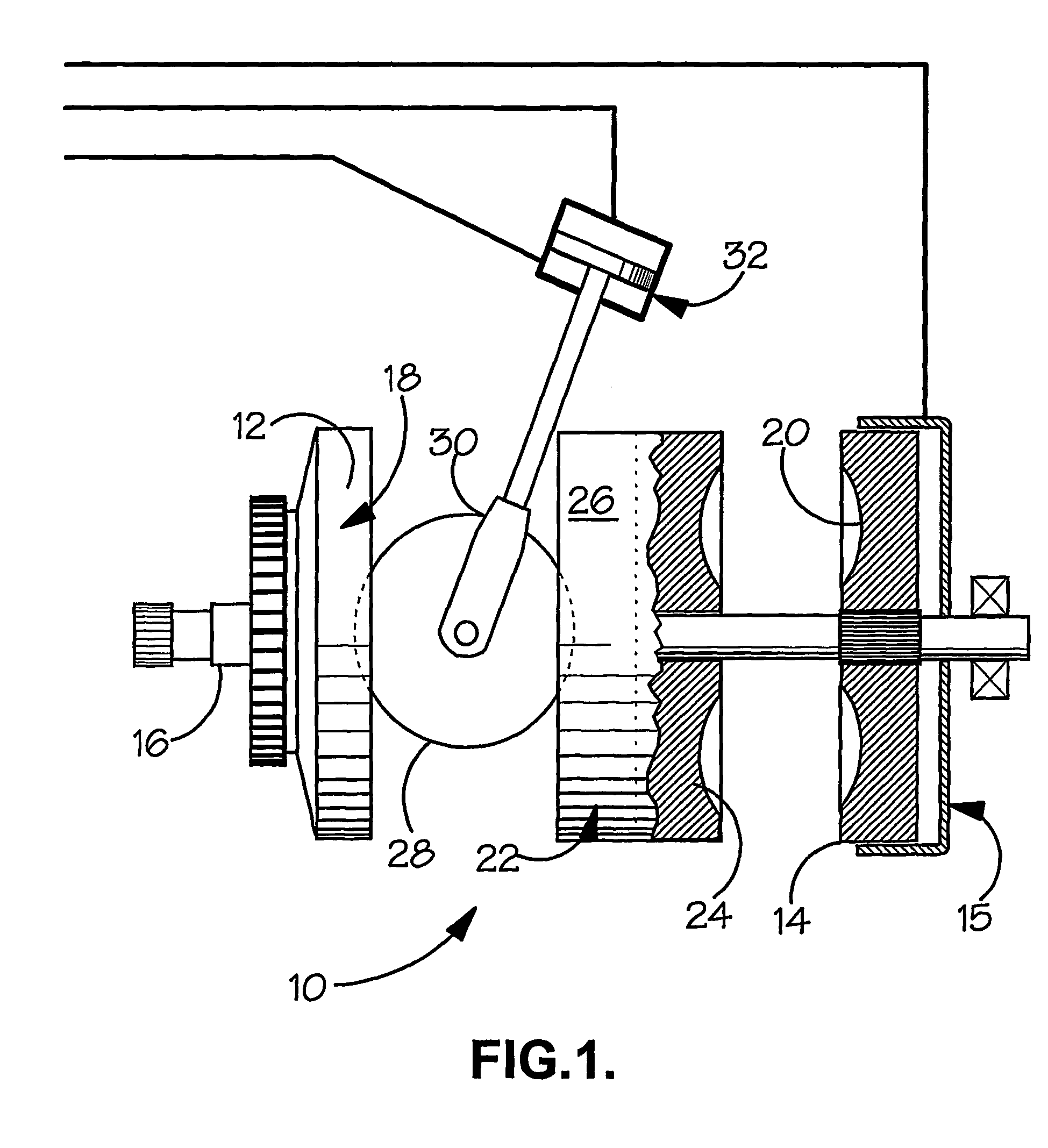
BACKGROUND OF THE INVENTION[0001]1. Field of the Invention[0002]The present invention relates generally to continuously variable transmissions and more specifically to hydraulic control thereof.[0003]2. Background Art[0004]The invention is particularly, although not exclusively, applicable to transmissions which incorporate a ratio varying unit (“variator”) of the toroidal-race rolling traction type to provide the required continuously-variable transmission ratio. Major components of a known variator 10 of the “full toroidal” type are illustrated in FIG. 1. Here, two input discs 12, 14 are mounted upon a drive shaft 16 for rotation therewith and have respective part toroidal surfaces 18, 20 facing toward corresponding part toroidal surfaces 22, 24 formed upon a central output disc 26. The output disc is journalled such as to be rotatable independently of the shaft 16. Drive from an engine or other prime mover, input via the shaft 16 and input discs 12, 14, is transferred to the outp...

Claims


Application Information

Patent Timeline
IPC IPC(8): B60W10/04F16H61/30B60W10/10F16H61/02F16H61/662F16H61/664
CPCF16H61/6648Y10T477/6243Y10T477/619F16H2061/6605
Inventor FULLER, JOHN WILLIAM EDWARD
Owner TOROTRAK (DEV) LTD
Learn More