
Head end receiver for digital data delivery systems using mixed mode SCDMA and TDMA multiplexing

a receiver and digital data technology, applied in the field of head end receivers for digital data delivery systems using mixed mode scdma and tdma multiplexing, can solve the problems of many sources of interference which can leak into upstream signals, and the system cannot fully live up to its promised potential, so as to improve performance, improve signal-to-noise ratio, and improve performance

Inactive Publication Date: 2006-05-23
GOOGLE TECH HLDG LLC
View PDF5 Cites 379 Cited by
  • Summary
  • Abstract
  • Description
  • Claims
  • Application Information

AI Technical Summary

Benefits of technology

[0015]When receiving SCDMA bursts, a CMTS receiver within the genus of the invention will be able to receive data transmitted simultaneously on the same frequency by multiple cable modems or other transmitters such as cellular phones, wireless modems or messaging services, any digital data carrying wireless or hardwired service with distributed transmitters transmitting to a single receiver, or satellite uplink or downlink transmitters with each burst spread by different spreading codes. This provides the advantage that more cable modems or cellular phones can be operating simultaneously which appears to the cable modems or cellular phones to be more virtual bandwidth, although the absolute bandwidth of the cable television or other shared transmission medium has not physically changed.
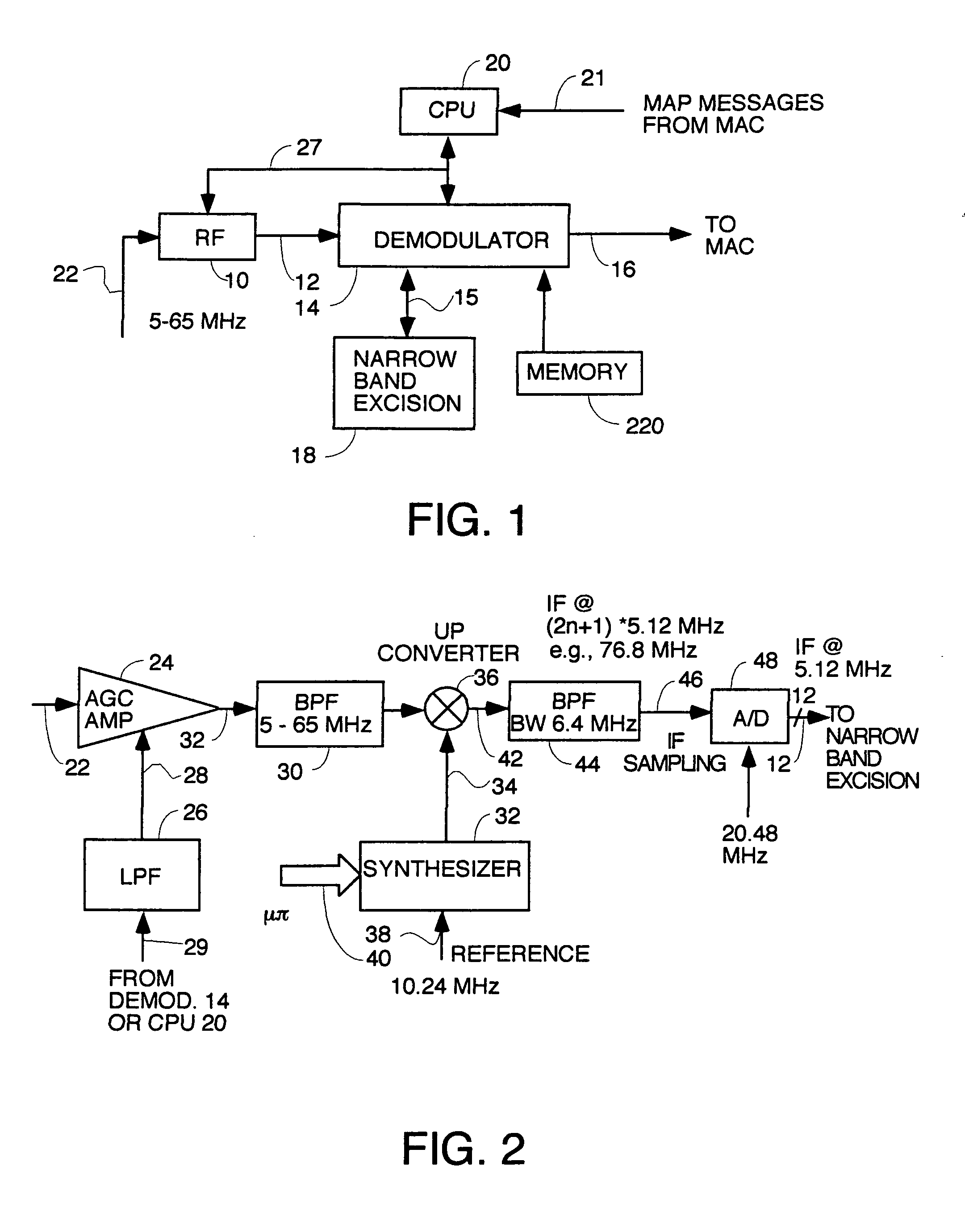
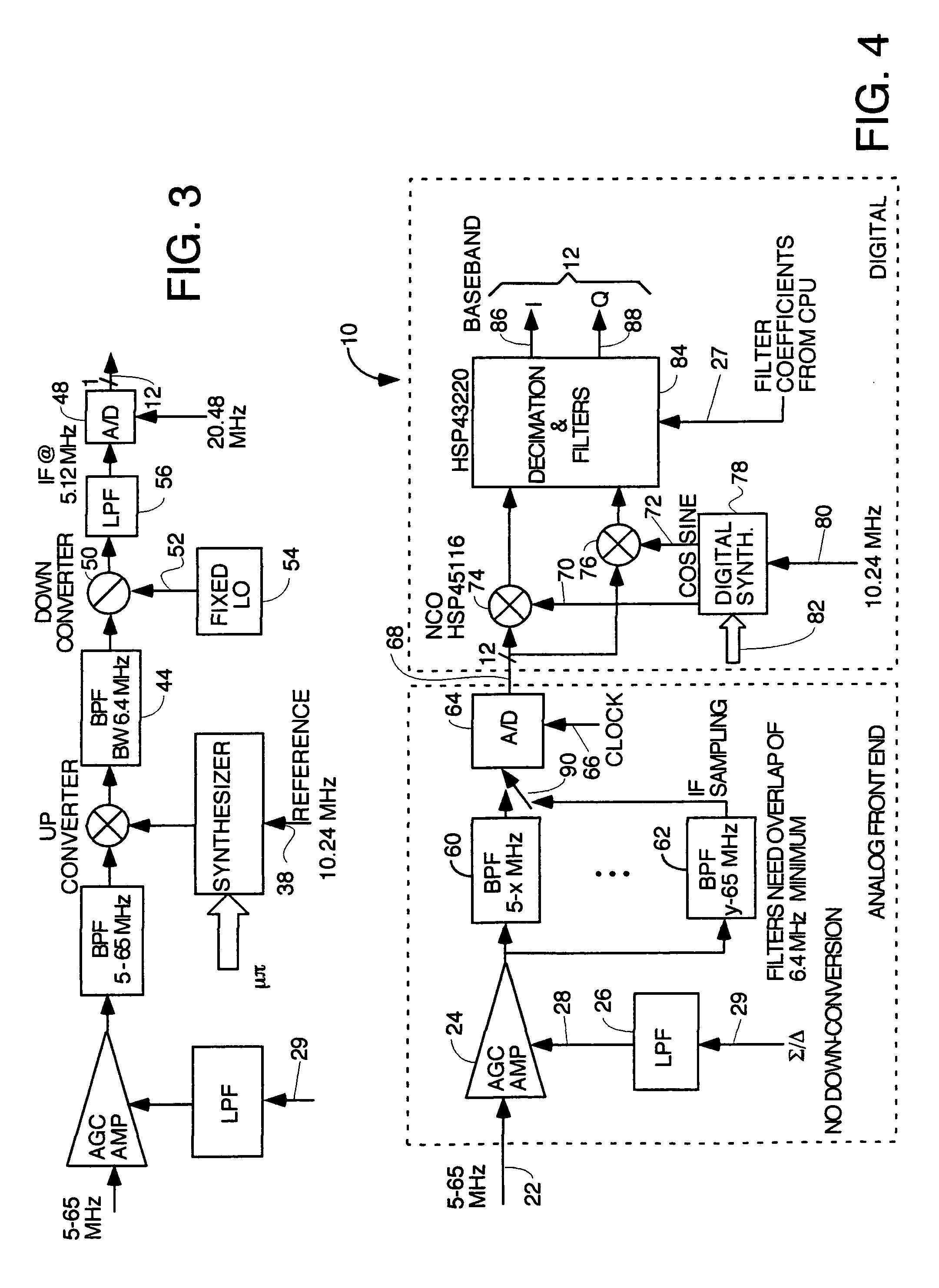
[0018]The following are the essential and optional elements of the demodulator section of every species within the genus of the invention, and at least the essential elements should be interpreted to be part of every claim. An impulse detector is optional to detect impulse noise and mark samples that are corrupted by impulse noise as erased. The impulse detectector is preferred to improve performance but is not essential. Likewise, a narrowband excision circuit coupled between the RF section and the demodulator section is optional to improve performance but is not essential. A front end AGC circuit in the demodulator is optional to allow the receiver to be used in digital cable headends or wireless systems, but is not essential if the only application is cable system headends. A decimation and programmable passband filter circuit should be included which has a bandwidth that is adjustable to match the symbol rate of the transmitted burst to reject noise outside the bandwidth of the selected carrier and burst if this function has not already been performed in the RF section. Optionally, the programmable passband filter is a matched filter to obtain better signal-to-noise (SNR) ratio. The programmable passband filter is essential for use in addition to the narrow passband filter in the RF section. The narrow passband filter in the RF section must have a bandwith to receive the highest symbol rate burst on a channel and reject all other channels. The programmable passband filter in the demodulator finishes the filtering job by having a passband that can be narrowed below 6.2 MHz to allow passband filtering of bursts with low symbol rates and bandwidths below 6.2 MHz. The decimation function is optional and serves to reduce the number of samples for bursts of lower symbol rate where a high number of samples are not needed.

Problems solved by technology

In the upstream where many cable modems (CMs) in homes and businesses transmit digital data to a cable modem termination system (CMTS) at the cable plant headend, there are many sources of interference which can leak into the upstream signals.
These sources include echoes from improperly terminated cable outlets, ignition noise, radio frequency interference generated by transmitters and household appliances, etc.
In some prior art cable modem distributed digital data delivery systems, these noise problems have been so intractable, that they led to the ultimate failure of the system to fully live up to its promised potential.

Method used


Image

  • Head end receiver for digital data delivery systems using mixed mode SCDMA and TDMA multiplexing
  • Head end receiver for digital data delivery systems using mixed mode SCDMA and TDMA multiplexing
  • Head end receiver for digital data delivery systems using mixed mode SCDMA and TDMA multiplexing

Examples


Embodiment Construction

[0038]Referring to FIG. 1, there is shown a block diagram of the preferred form of receiver according to the teachings of the invention. The functions the various blocks must perform to be DOCSIS compatible are defined in published DOCSIS specifications which are available publicly to Cable Labs members at www.cablelabs.com. All such specifications and, specifically, SP-RFIv1.1-I05-000714 are hereby incorporated by reference.

[0039]In a typical CMTS, a receiver like the one shown in FIG. 1 would be assigned to receive data in one or more frequency channels. Typically, there would be a plurality of frequency division multiplexed (hereafter FDMA) channels transmitted upstream in a band from 5 to 65 MHz, each of which carries multiple logical channels of data from different sources. Each logical channel within an FDMA channel would be multiplexed from the other channels by SCDMA or TDMA. In the preferred embodiment, the upstream FDMA channels have selectable bandwidths of 6.4, 3.2, 1.6,...


PUM


Abstract

A pipelined digital data receiver for a cable TV headend which is capable of receiving DOCSIS 1.0 or 1.1 or advanced PHY TDMA or SCDMA bursts having programmable symbol rates and programmable modulation types as well as a host of other burst parameters such at Trellis code modulation on or off, scrambling on or off, various values for Reed-Solomon T number and codeword length. The receiver has an RF section to filter and digitize incoming RF signals. It also has an input section to detect impulse noise and do match filtering and despread SCDMA bursts. A timing recovery section recovers the symbol clock and detects the start of bursts and collisions. A rotational amplifier and equalizer calculate and track gain, phase and frequency offsets and correct symbols and calculates equalization coefficients. A decoder section decodes TCM and non TCM bursts, and a Reed-Solomon decoder section reconstructs RS codewords and uses them to error correct the payload data.

Description

BACKGROUND OF THE INVENTION[0001]Cable modem usage to send and receive digital data is on the rise with the buildout of high bandwidth cable TV systems with spare bandwidth in which to send high speed digital data such as internet traffic. An emerging standard for cable modems is currently under development which defines cable modem systems wherein mixed mode upstream transmissions can be received. The reason this is important is that legacy cable systems exist such as DOCSIS 1.0 and 1.1 that deliver time division multiplexed (hereafter TDMA) digital data bursts over cable television media. However, there are significant advantages to using code division multiplexing, and especially synchronous code divsion multiplexed (hereafter SCDMA) bursts. Specifically, the use of SCDMA provides significant “code gain” to suppress the negative effects caused by both narrowband interference and Gaussian noise suppression. In the upstream where many cable modems (CMs) in homes and businesses tran...

Claims


Application Information

Patent Timeline
Patent Type & Authority Patents(United States)
IPC IPC(8): H04B7/212H04B3/06H04B7/005H04L5/02H04L25/03H04L27/00
CPCH04L5/026H04L27/0008H04L25/03006
Inventor AZENKOT, YEHUDALIND, PAUL ALANGRIMWOOD, MICHAELRAKIB, SELIM SHLOMO
Owner GOOGLE TECH HLDG LLC
Learn More