
Apparatus and method for treating a liquid

a liquid treatment and apparatus technology, applied in the field of chemical mixing, can solve the problems of increasing the cost of tertiary treatment, increasing the cost of secondary treatment, and increasing the problem of wastewater treatment and disposal

Inactive Publication Date: 2006-05-16
INFLOWSION
View PDF70 Cites 36 Cited by
  • Summary
  • Abstract
  • Description
  • Claims
  • Application Information

AI Technical Summary

Benefits of technology

[0026]A specific embodiment of the present invention is shown in the attached drawings. For the purpose of summarizing the invention, the invention relates to an improved method and apparatus for treating a liquid with a first and a second chemical. A liquid pump is provided for pumping the liquid into a first inlet port of an intake manifold. A second inlet port of the intake manifold introduces a first chemical into the liquid. A first static mixing device comprises a spirally twisted tube forming a plurality of helixes. An inlet port of the first static mixing device is connected in

Problems solved by technology

The treatment and disposal of wastewater is an ever increasing problem as the population and subsequent urbanization increases.
Although the tertiary level of treatment is expensive, very often doubling the cost of the secondary treatment, the effluent water discharged from the tertiary level of treatment is of near drinking water quality.
Unfortunately, chlorine gas leaves a chlorine residue that may have adverse effects on aquatic life.
The prior art addresses many of the concerns in the treatment of wastewater, however several problems associated with these processes have not been answered.
Among these problems is the build-up of material on and around the internal mechanisms associated with the process.

Method used


Image

  • Apparatus and method for treating a liquid
  • Apparatus and method for treating a liquid
  • Apparatus and method for treating a liquid

Examples


Embodiment Construction

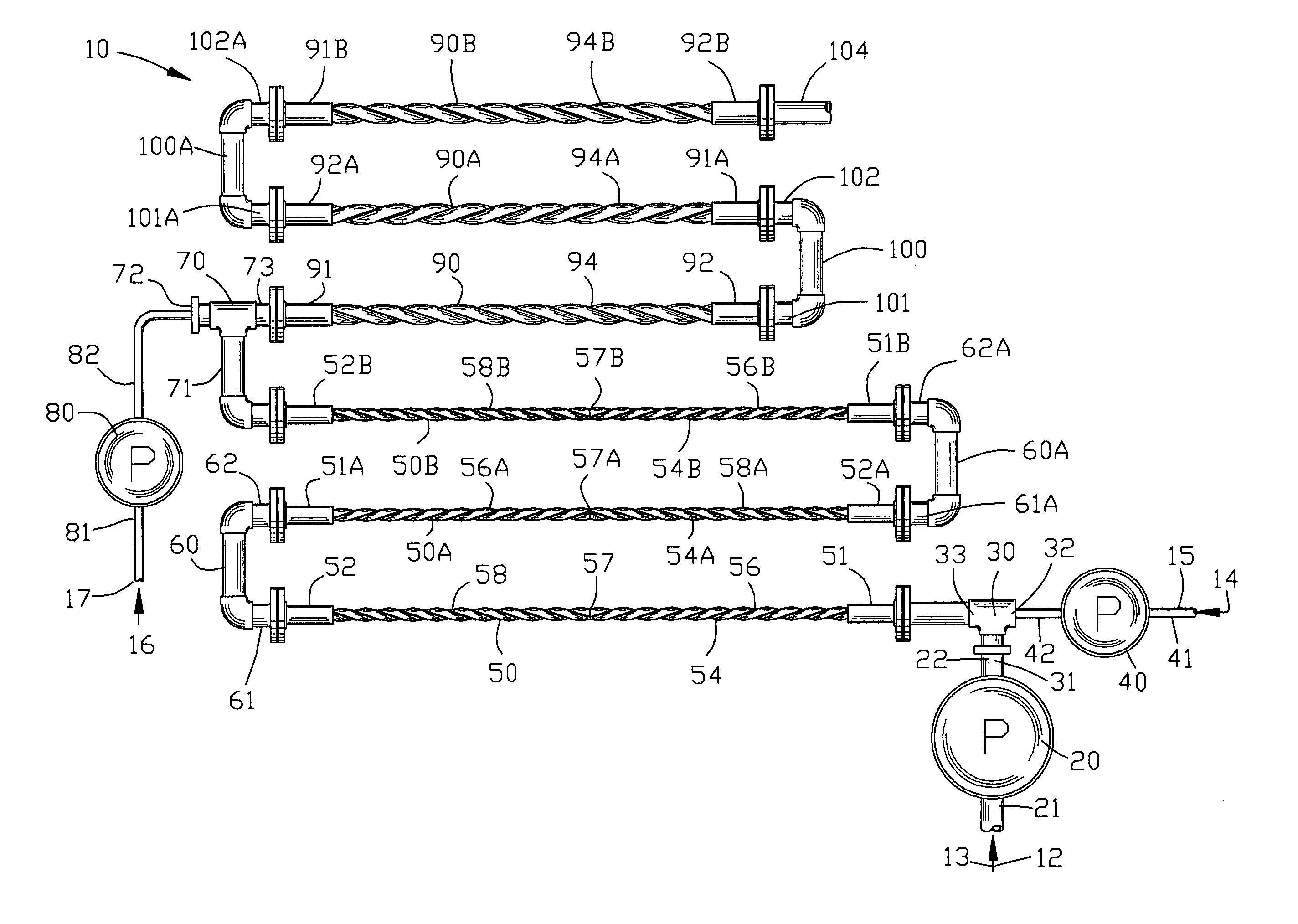
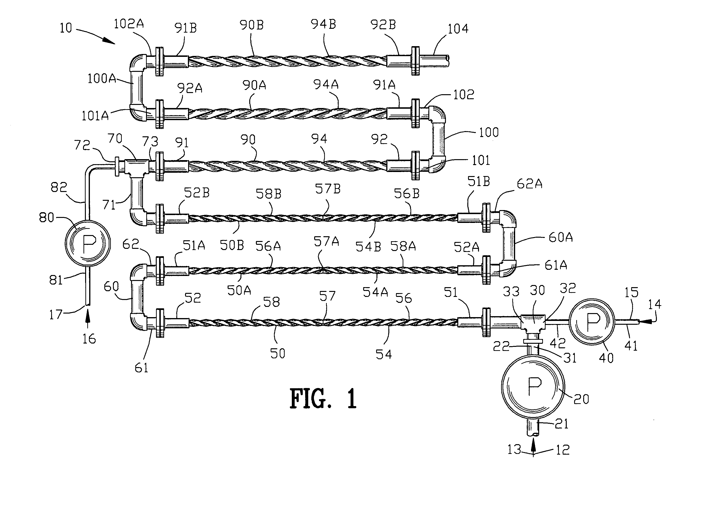
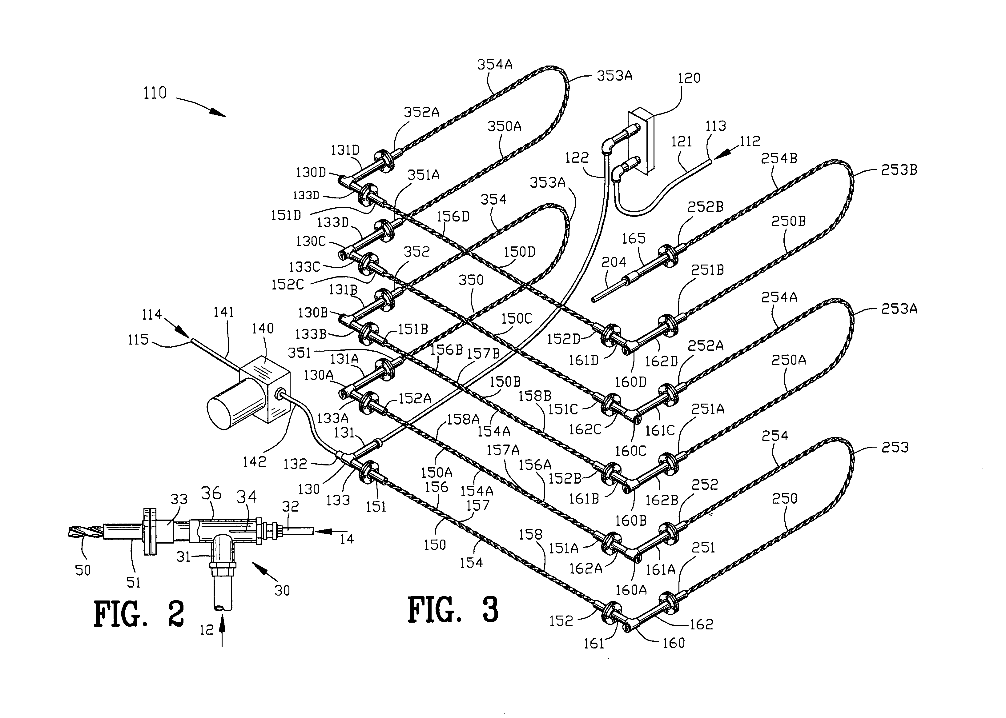
[0042]FIG. 1 illustrates a first embodiment of an apparatus 10 for treating a liquid 12 from a liquid source 13 with a first chemical 14 from a first chemical source 15 and a second chemical 16 from a second chemical source 17. The apparatus 10 is suitable for treating a liquid 12 such as wastewater in a secondary wastewater treatment.

[0043]A pump 20 comprises a pump inlet 21 and a pump outlet 22 with the pump inlet 21 being connected to the liquid source 13. An intake manifold 30 comprises a first inlet port 31, a second inlet port 32 and an outlet port 33. The liquid pump outlet 22 is in fluid communication with the first inlet port 31 of the intake manifold 30.

[0044]A first chemical pump 40 comprises a pump inlet 41 and a pump outlet 42 with the pump inlet 41 being connected to the first chemical source 15. The first chemical 14 is pumped from the first chemical source 15 through the first chemical pump inlet 41 by the first chemical pump 40. The pump outlet 42 is in fluid commun...


PUM

PropertyMeasurementUnit
Flow rateaaaaaaaaaa

Abstract

An apparatus and method is disclosed for treating a liquid with a first and a second chemical. A liquid to be treated flows into a first inlet port of an intake manifold. A second inlet port of the intake manifold introduces a first chemical into the liquid. A first static mixing device comprising a spirally twisted tube forming a plurality of helixes and having an inlet port connected in fluid communication with an outlet port of the intake manifold is provided for mixing the first chemical with the liquid. The outlet port of the first static mixing device is connected to a first inlet port of an interconnecting manifold. A second inlet port of the interconnecting manifold introduces a second chemical into the liquid. A second static mixing device has an inlet in fluid communication with an outlet port of the interconnecting manifold for mixing the second chemical with the liquid and for eluting the treated liquid from an outlet port of the second static mixing device.

Description

CROSS-REFERENCE TO RELATED APPLICATIONS[0001]This application claims benefit of U.S. Patent Provisional application Ser. No. 60 / 431,689 filed Dec. 5, 2002. AU subject matter set forth in provisional application Ser. No. 60 / 431,689 is hereby incorporated by reference into the present application as if fully set forth herein.BACKGROUND OF THE INVENTION[0002]1. Field of the Invention[0003]This invention relates to chemical mixing, and more particularly to the treatment of a liquid with a chemical.[0004]2. Background of the Invention[0005]The treatment and disposal of wastewater is an ever increasing problem as the population and subsequent urbanization increases. Ultimate disposal of wastewater is either to discharge into a surface body of water or in some areas subsurface disposal is utilized. In both instances, treatment of wastewater prior to disposal is mandatory to prevent both the water quality and the health and safety of the public to be compromised. Wastewater contains, among ...

Claims


Application Information

Patent Timeline
IPC IPC(8): C02F1/52
CPCB01F3/0861B01F5/0646C02F1/5281B01F5/0647B01F2015/0221B01F2215/0036B01F23/45B01F25/4331B01F25/433B01F35/715B01F2101/2204
Inventor LILES, JOHN KEVINSCHMIDBAUER, GREGORY A.
Owner INFLOWSION
Learn More