Method for controlling a ventilator, and system therefor

Inactive Publication Date: 2006-05-09
AVENT INC
View PDF8 Cites 187 Cited by
  • Summary
  • Abstract
  • Description
  • Claims
  • Application Information

AI Technical Summary

Benefits of technology

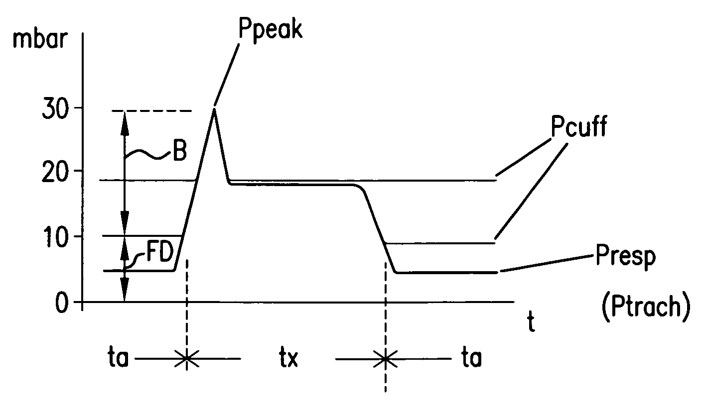
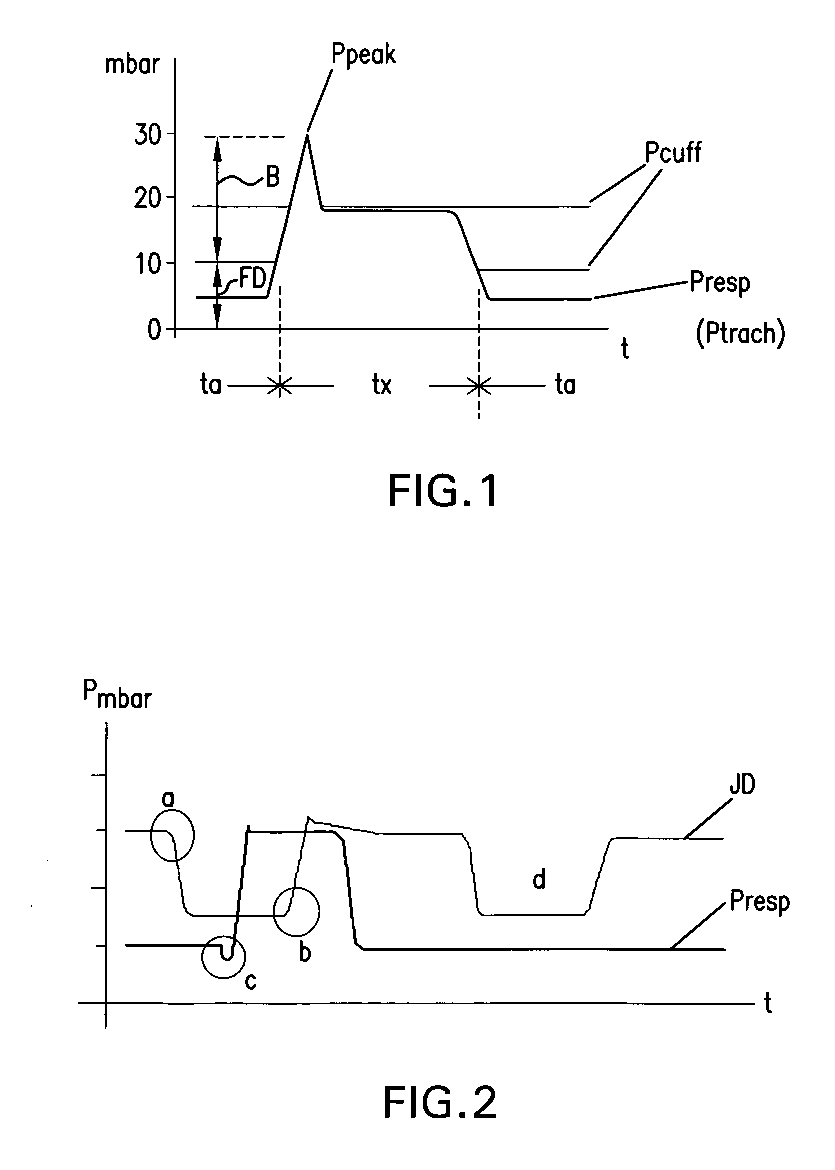
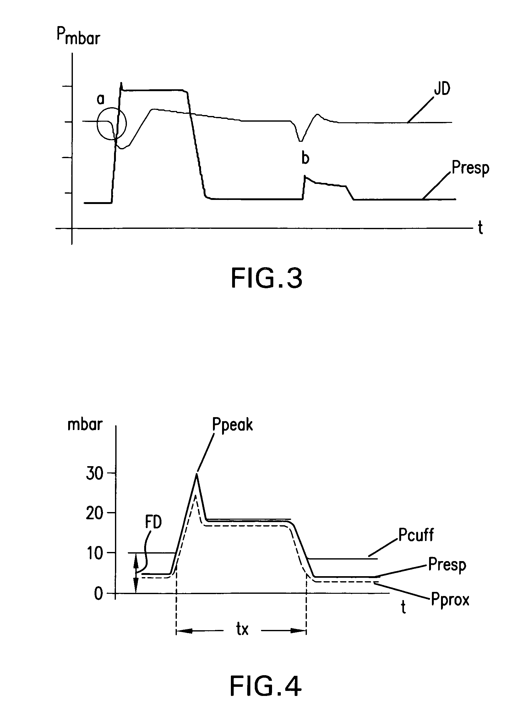
[0015]According to this invention, there is a method and a system for assisted or controlled ventilation by a ventilator and its control using tracheal tubes and tracheostomy tubes, which have microthin-walled cuffs or gastric probes that are equipped with a microthin-walled balloon. With the microthin-walled cuff or the esophageal balloon, the tracheobronchial airway pressure fluctuations, or the fluctuations in the intrathoracic pressure are detected and used to improve the interaction of the patient and the ventilator (respirator).
[0019]According to this invention, particular mechanical properties of such microthin balloon films define one important field of use for controlling ventilators. The microthin-walled cuff or balloon of a ventilator tube or gastric probe makes it possible to detect pressure fluctuations inside the tracheobronchial airway, or inside the chest (intrathoracic pressure) with high measurement precision and over a wide amplitude range, largely without latency. The measurement option of such extremely thin-walled balloon films is possible due to their low operating pressures (fill pressures). Even at fill pressure values of 10 mbar, highly efficient sealing off from secretions, for example, or from the respiration pressure exerted on the balloon can be achieved with such balloons, even if the exerted pressure briefly exceeds the fill pressure of the balloon. Also, the membrane-like nature of such films makes it possible to detect even the tiniest pressure fluctuations inside the balloon, or structures communicating transmurally with the balloon, and submit them to a measurement.
[0022]According to this invention, by detecting the actually prevailing airway pressure in the tracheobronchial region, it is possible to control the ventilator-controlled ventilation gas flow to avoid overpressure situations inside the deep airways.

Problems solved by technology

It is therefore difficult to draw a conclusion about the central airway pressure actually achieved in the trachea from the ventilation pressure measured inside the ventilator.
A disadvantage in this measuring method for detecting the tracheobronchial airway pressure using pressure hoses in accordance with European Patent Disclosure EP 0 459 284 B1 is that the thin pressure measuring hoses, placed in the trachea in the tracheal tube, rapidly plug up with secretions on their end oriented toward the bronchial tube, and thus the central airway pressure can no longer be measured reliably.
An apparatus according to European Patent Disclosure EP 0 459 284 B1 for measuring the tracheobronchial airway pressure using pressure measuring hoses or pressure measuring conduits that are filled with fluid has not yet gained acceptance, mainly because of the high cost of equipment and the expected vulnerability to malfunction, or the resultant measurement imprecision.
This apparatus for detecting the central airway pressure again has the disadvantage that the pressure measuring cannula, which is open on its end toward the bronchial tube, easily becomes plugged with secretions, making reliable, artifact-free measurement and regulation of the ventilator impossible.
Such a method is technologically complex and once again, because of deposits of secretion on the sensor, is adequately invulnerable to malfunction.

Method used


Image

  • Method for controlling a ventilator, and system therefor
  • Method for controlling a ventilator, and system therefor
  • Method for controlling a ventilator, and system therefor

Examples


Embodiment Construction

[0032]FIG. 6 shows a function diagram for assisted or controlled ventilation of a patient P, into whose trachea a tracheal tube 1, shown in FIG. 5, is introduced, in order to introduce the breathing gas AG and detect the airway pressure by suitable measuring instruments. On the one hand, the intra-cuff pressure Pcuff is detected continuously and delivered to a control device ST for the ventilator BG. The control device includes a measured value and signal processor with an evaluation unit, and in accordance with the detected intra-cuff pressure Pcuff, it furnishes a signal S for controlling the ventilator. This signal is used, for example to control either the trigger (tripping a ventilation stroke) in assisted ventilation, or the pressure limiting function (maximal or “upper ventilation pressure”), for example, which is included in all modes of ventilation. Accordingly, with this signal S, the supply of breathing gas AG from the ventilator BG to the patient P is controlled. It is a...


PUM


Abstract

A method for controlling breathing gas flow of a ventilator for assisted or controlled ventilation of a patient as a function of a tracheobronchial airway pressure of the patient. A ventilator tube, such as a tracheal tube or tracheostomy tube, can be introduced into a trachea of the patient and subjected to the breathing gas, and has an inflatable cuff and at least one lumen that is continuous from a distal end of the tube to a proximal end of the tube. An apparatus detects an airway pressure, in which the tracheobronchial airway pressure is ascertained by continuous or intermittent detection and evaluation of an intra-cuff pressure prevailing in the cuff of the tube inserted into the trachea. The breathing gas flow of the ventilator is controlled as a function of the intra-cuff pressure detected.

Description

BACKGROUND OF THE INVENTION[0001]1. Field of the Invention[0002]This invention relates to a method for controlling the breathing gas flow of a ventilator for assisted or controlled ventilation of a patient as a function of the tracheobronchial airway pressure of the patient, having a ventilator tube, such as a tracheal tube or tracheostomy tube, that can be introduced into the trachea or the patient and subjected to the breathing gas, that has an inflatable cuff and at least one lumen that is continuous from the distal end of the tube to the proximal end of the tube. This invention also relates to an apparatus for detecting the airway pressure, in which the tracheobronchial airway pressure is determined by continuous or intermittent detection and evaluation of the intra-cuff pressure prevailing in the cuff of the tube inserted into the trachea, and the breathing gas flow of the ventilator is controlled as a function of the intra-cuff pressure detected.[0003]This invention also relat...

Claims


Application Information

Patent Timeline
IPC IPC(8): A61M16/00A61M16/04
CPCA61M16/044A61M16/0452A61B5/037A61M2210/105A61M16/0409A61M16/0415A61B5/087A61M16/024A61M2016/0027A61M2205/3344
Inventor GÖBEL, FRED
Owner AVENT INC
Why Eureka
Try Eureka