Multilevel speed regulation jack

a technology of multi-level speed regulation and jack, which is applied in the direction of clutches, fluid couplings, lifting devices, etc., can solve the problems of time and effort consumption, slow jacking process, etc., and achieve the effect of fewer speed ranges, different load capacities, and more speed ranges

Inactive Publication Date: 2006-05-09
FAN QUN
View PDF4 Cites 8 Cited by
  • Summary
  • Abstract
  • Description
  • Claims
  • Application Information

AI Technical Summary

Benefits of technology

[0005]The present invention is a multilevel speed regulation jack system, which automatically switches between different jacking speeds based on the load signal it senses. The system of the invention can therefore provide increased jacking efficiency.
[0019]In the present invention, the system jacks up loads with different speeds based on the loads. This speed switching automatically takes place without any external operation. The jack of the present invention has a higher jacking efficiency and its operation is simple and fast. The system jacks up loads with less force and less time.
[0021]The design of the system can be based on load application. The user can choose the system according to load application. If the load is relatively small, the user can choose a jack system with fewer speed ranges. If the load is big, the user can choose a jack system with more speed ranges. The present invention works at different speeds and different load capacities. At each speed, it works with a particular jacking capacity, as if it was an individual conventional jack of that capacity. The merit of the multiple speed jack system is that only one multiple speed jack is needed to jack up loads of many different weight ranges during operation, instead of switching many conventional jacks of different load capacities. The present invention actually combines many load capacities into one system without a radical departure from the basic structure of a conventional jack. The system also automatically switches its capacity based on the load exerted on it. The present invention provides easier and simpler jacking operations and increases work efficiency and tool utilization.

Problems solved by technology

The jacking process is slow, as well as time and effort consuming.

Method used


Image

  • Multilevel speed regulation jack
  • Multilevel speed regulation jack
  • Multilevel speed regulation jack

Examples


embodiment 1

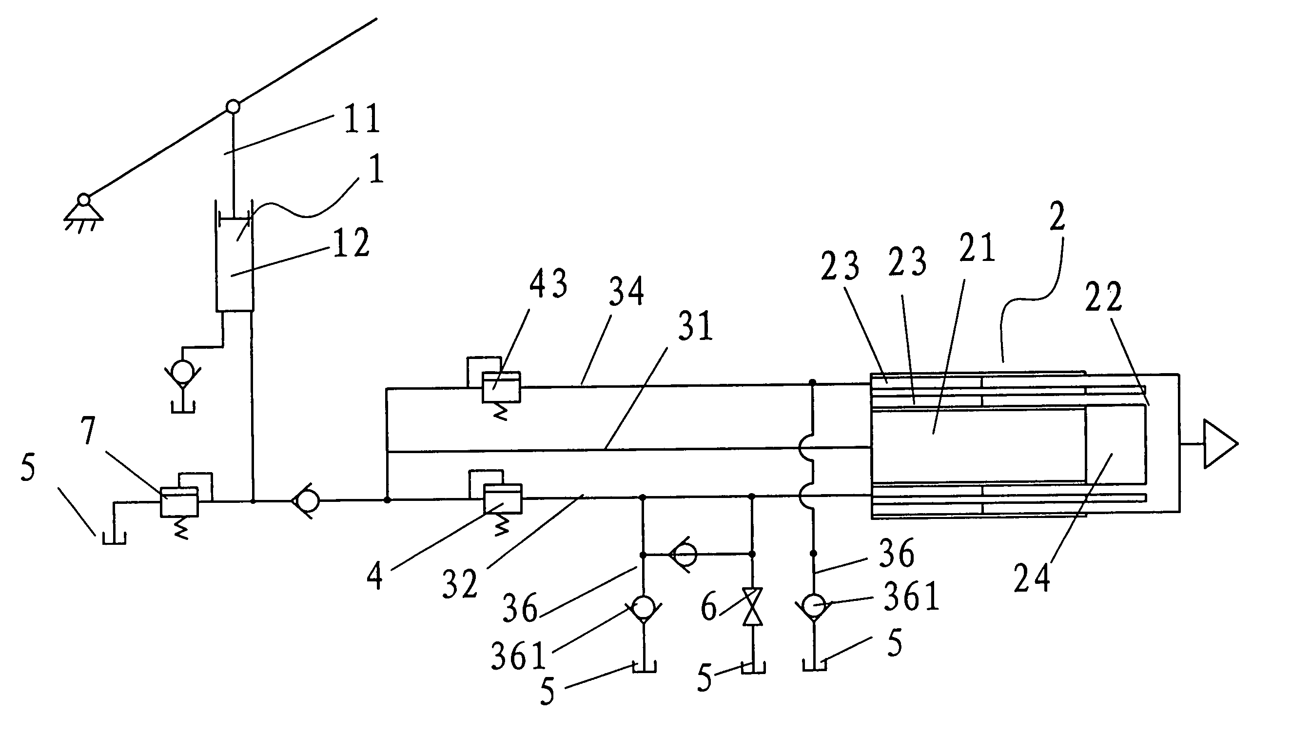
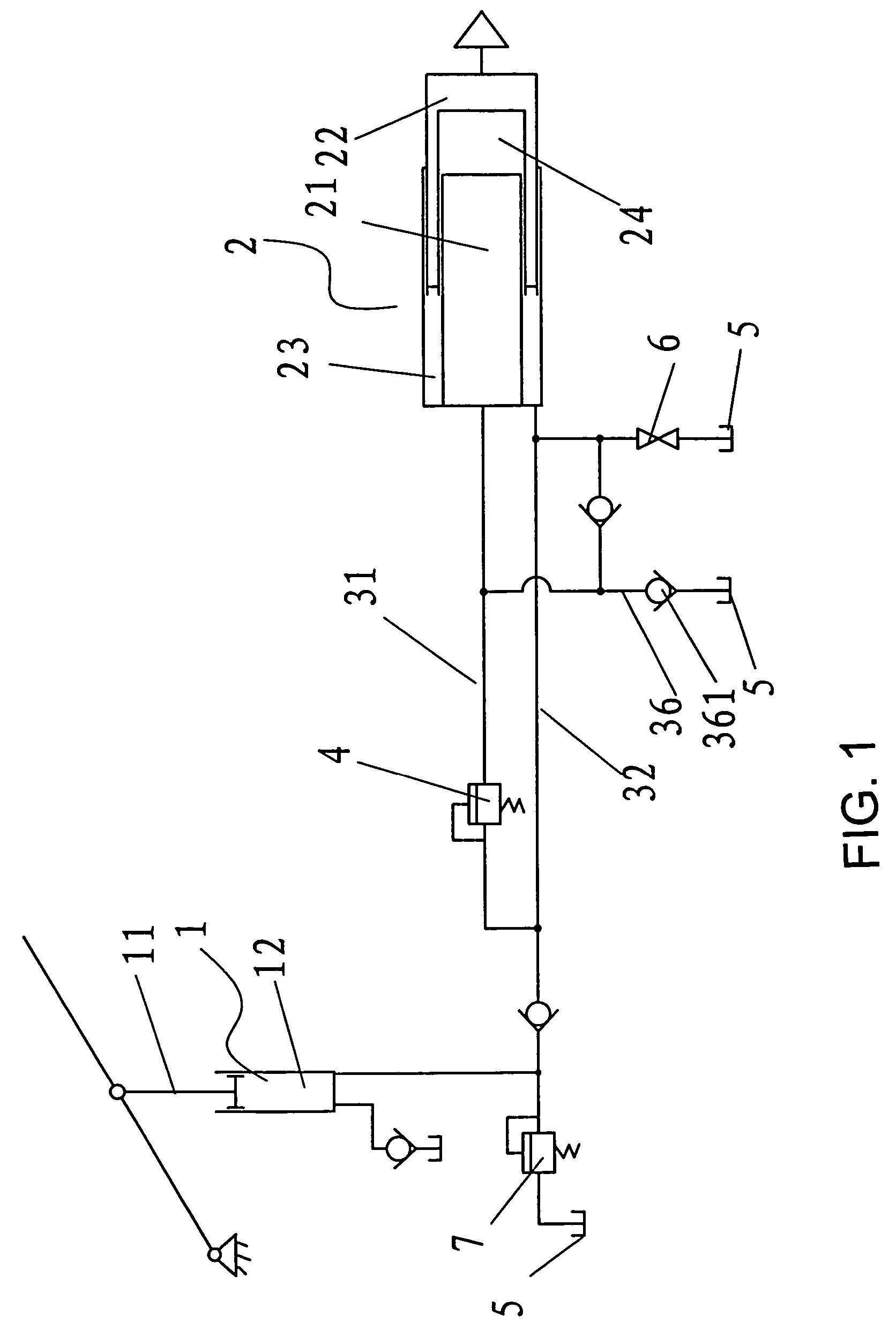
[0042]As illustrated in FIG. 1, this embodiment of the present invention has one annular in-flow oil chamber 23. Control valve 4 may be installed in fluid channel 31, which is connected to the central in-flow oil chamber. The control valve controls the connection state of fluid channel 31 based on the load signal it senses. When there is a zero or light load, pressing down piston rod 11 in input cylinder 1 forces the fluid in an out-flow chamber 12 inside input cylinder 1 to flow into annular in-flow chamber 23 via fluid channel 32. The fluid pushes piston 22 in output cylinder 2 through its annular end surface as thrust area at a speed V1. Because the thrust area of piston 22 in output cylinder 2 in this example is small, V1 is large and piston 22 moves fast, and the system has a high jacking efficiency.

[0043]As the load increases, the pressure of fluid increases accordingly and eventually it opens control valve 4 in fluid channel 31, and some of the fluid is pumped into central in...

embodiment 2

[0049]As illustrated in FIG. 3, in this embodiment of the present invention, output cylinder 2 has one annular in-flow oil chamber 23. Control valve 4 is installed in fluid channel 31 connected to central in-flow oil chamber 24. The system has at least one other input cylinder 1′ unidirectionally connected to annular in-flow oil chamber 23 through fluid channel 33. Fluid channel 33 is connected to oil reservoir 5 via control valve 42. The system may have one or more additional input cylinders 1′. Each addition of an input cylinder 1′ adds one speed range to the jack system. Using a system of only one additional input cylinder 1′ as an example, the working process and principle of speed switching is detailed in the following.

[0050]With a zero or light load, by pressing down piston rod 11 in the input cylinder 1, both input cylinders 1 and 1′ force fluid oil into annular in-flow oil chamber 23 through fluid channels 32 and 33, respectively. The pressure of the fluid pushes forward pis...

embodiment 3

[0057]The basic structure and working principle of this embodiment is similar to those of the embodiment 1, and therefore will not be repeated here.

[0058]The difference between this embodiment and the embodiment 1 is illustrated in FIG. 5. Cylinder body 21 of output cylinder 2 may have two or more annular spaces, and piston 22 has correspondingly two or more tube sleeves. Each sliding sleeve is movably positioned in its corresponding annular space to form an individual annular in-flow oil chamber 23. Each annular in-flow oil chamber 23 is connected to input cylinder 1 through a parallel fluid channel. In each fluid channel a sequence-programmed and threshold-preset control valve is installed. The control valve controls the connection state of the fluid channel based on the load signal it senses. Each addition of an annular in-flow oil chamber 23 adds at least one speed range to the system, making it a multiple speed jack system. Using a system of two annular in-flow oil chambers 23 ...


PUM


Abstract

A multilevel speed regulation jack includes an input oil cylinder, an output oil cylinder, and a fluid conduit member between the cylinders. The output oil cylinder includes a cylinder body containing an annular space and a tube piston, which fits in the annular space. A sliding sleeve of the tube piston is movably positioned in the annular space. An annular in-flow oil chamber is formed between the end annular surface of the tube piston and the cylinder body, and a central in-flow oil chamber is formed between the inner central surface of the piston and the cylinder body. The fluid conduit member includes at least two parallel fluid channels connected to the central in-flow oil chamber and the annular in-flow oil chamber, respectively. A control valve in one of the fluid channels opens / closes the channel. The jack can automatically switch between different jacking speeds based on the load sensed by the system and therefore has a high jacking efficiency.

Description

FIELD OF THE INVENTION[0001]The present invention relates to a device that jacks a load to a predetermined height, and more particularly to a multilevel speed regulation jack system.BACKGROUND OF INVENTION[0002]Hydraulic jacks are common devices used in daily life for jacking a load to a predetermined height with a considerably small force. The working principle of the hydraulic jack is as follows. An applied small force moves an input piston of small cross-sectional area and pushes fluid oil into an output oil cylinder, which then forces an output piston of large cross-sectional area to jack up the load.[0003]According to the law of energy conversion, the path of the input piston is far longer than that of the output piston. Therefore the input piston must be repeatedly pumped to jack a load to a certain height. During the jacking process, each stroke of the input piston moves the output piston the same distance, regardless of the load. Therefore the same number of pumping strokes ...

Claims


Application Information

Patent Timeline
Patent Type & Authority Patents(United States)
IPC IPC(8): F16D31/02B66F3/42F15B3/00F15B7/04
CPCB66F3/42F15B7/04F15B3/00
Inventor FAN, QUN
Owner FAN QUN
Why Eureka
Try Eureka