Screw rod positioning device of elevator

A technology of positioning mechanism and hoist, applied in the direction of hoisting device, etc., can solve the problems of poor positioning effect, affecting service life, poor lifting efficiency, etc., and achieve the effect of labor-saving operation, easy manufacture, and reasonable structure

Active Publication Date: 2009-06-24
NINGBO TIANYI SHAFT
View PDF0 Cites 0 Cited by
  • Summary
  • Abstract
  • Description
  • Claims
  • Application Information

AI Technical Summary

Problems solved by technology

[0003] The present invention mainly solves the technical problems existing in the prior art, such as the poor positioning effect of the screw in the pipe body of the elevator, which leads to poor lifting efficiency, affecting the service life, inconvenient operation, etc., and provides a screw positioning mechanism for the elevator

Method used


Image

  • Screw rod positioning device of elevator

Examples


Embodiment

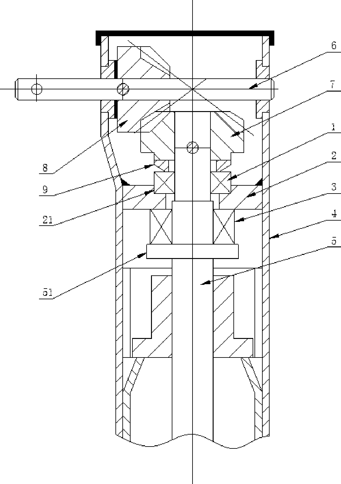
[0011] Embodiment: A screw positioning mechanism of a hoist, including a hollow pipe body 4 and an input shaft 6 and a screw 5 arranged thereon. The input shaft 6 and the screw 5 are perpendicular to each other and are driven by a pair of bevel gears 7 and 8. connection, the pipe body 4 is fixed with a support plate 2, the middle part of the support plate 2 is provided with a through hole and is sleeved outside the screw rod 5 through the through hole; The connected centripetal bearing 1, the other side is a plane and is provided with a planar bearing 3 that is rotationally connected with the boss 51 on the screw 5; The plane bearings 3 on both sides, the radial bearing 1 and the gear 7 constitute axial positioning. The fixing method of the support plate 2 and the pipe body 4 is welding. The support plate 2 is provided with a groove 21 for installing the radial bearing 1 . A washer 9 is arranged between the radial bearing 1 and the end face of the gear 7 .


PUM


Abstract

The invention relates to a screw rod positioning mechanism for a hoisting machine. The accuracy of verticality of a screw rod in a pipe body of the hoisting machine is greatly improved by setting axial and radial positioning at the input end of the screw rod, so as to improve the jacking efficiency of the hoisting machine, prolong the service life and improve the convenience of operation.

Description

technical field [0001] The invention relates to a small manual hoist, in particular to a screw positioning mechanism of the hoist. Background technique [0002] A small manual hoist that adopts a lifting mechanism including a lifting sleeve driven by a screw for rigid jacking belongs to a jacking machine, and is mainly used for lifting and conveying various heavy objects. It is used in daily life. There is also a wide range of applications; for small manual hoists with this structure, the driving force of the screw to push the lifting mechanism comes from the input shaft of its gear transmission, and the screw rotates under the transmission of the input shaft, so that under the action of the thread of the screw Drive the lifting mechanism to move up and down in the elevator tube body; at present, the support plate provided on the gear end of the screw is not connected to the elevator tube body, and is mainly used for one-way limit so that the gears keep the meshing distance ...

Claims


Application Information

Patent Timeline
Patent Type & Authority Applications(China)
IPC IPC(8): B66F3/08B66F3/16
Inventor 叶培玉邱明刚
Owner NINGBO TIANYI SHAFT
Why Eureka
Try Eureka