Automatic jacking tower crane structure

A tower crane and automatic technology, applied in the direction of cranes, etc., can solve the problems of increasing the lifting resistance of the hydraulic cylinder, shaking, and the adjustment balance is not in place, so as to improve the lifting efficiency, improve the use effect, and reduce the effect of the process.

Pending Publication Date: 2022-07-12
JIANGXI ZHONGTIAN INTELLIGENT EQUIP CO LTD
View PDF0 Cites 0 Cited by
  • Summary
  • Abstract
  • Description
  • Claims
  • Application Information

AI Technical Summary

Problems solved by technology

Before raising the height of the tower, workers need to adjust the position of the lifting trolley to balance the tower. This process is cumbersome and time-consuming
Before the balance adjustment, it is also necessary to adjust the gap between the 16 guide wheels on the jacking frame and the tower section to 2 mm to 5 mm, otherwise, it is very easy to have problems caused by inaccurate or deformation of the tower section during jacking. Stuck to increase the lifting resistance of the hydraulic cylinder
In addition, because there is a gap between the guide wheel and the tower section, it will shake during the lifting process due to improper adjustment and balance
[0004] The adjustment balance before jacking and the gap adjustment between the guide wheel and the tower section need to be strictly followed by the operating procedures, which is less efficient for the intelligent unmanned jacking of the tower crane

Method used


Image

  • Automatic jacking tower crane structure
  • Automatic jacking tower crane structure
  • Automatic jacking tower crane structure

Examples


Embodiment Construction

[0038] The accompanying drawings are schematic diagrams of the implementation of the present invention, so as to facilitate the understanding of the operation principle of the structure. The specific product structure and proportions can be determined according to the use environment and conventional techniques.

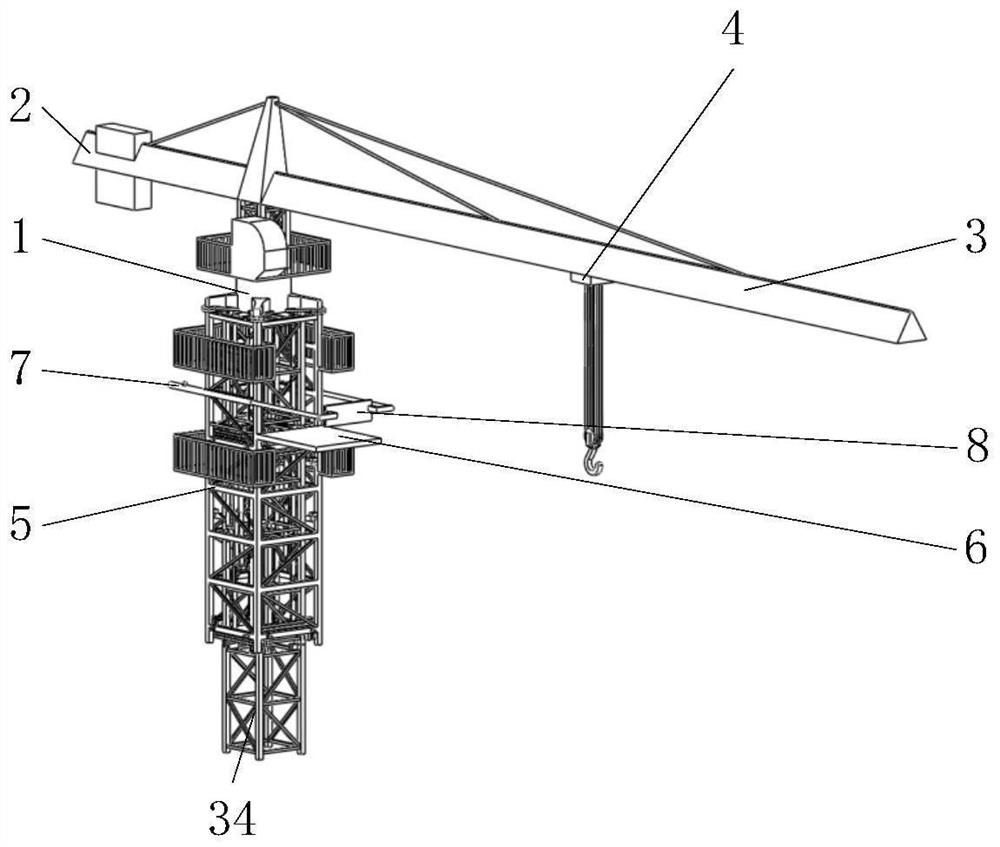
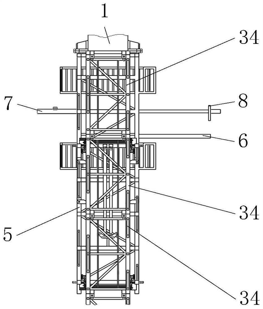
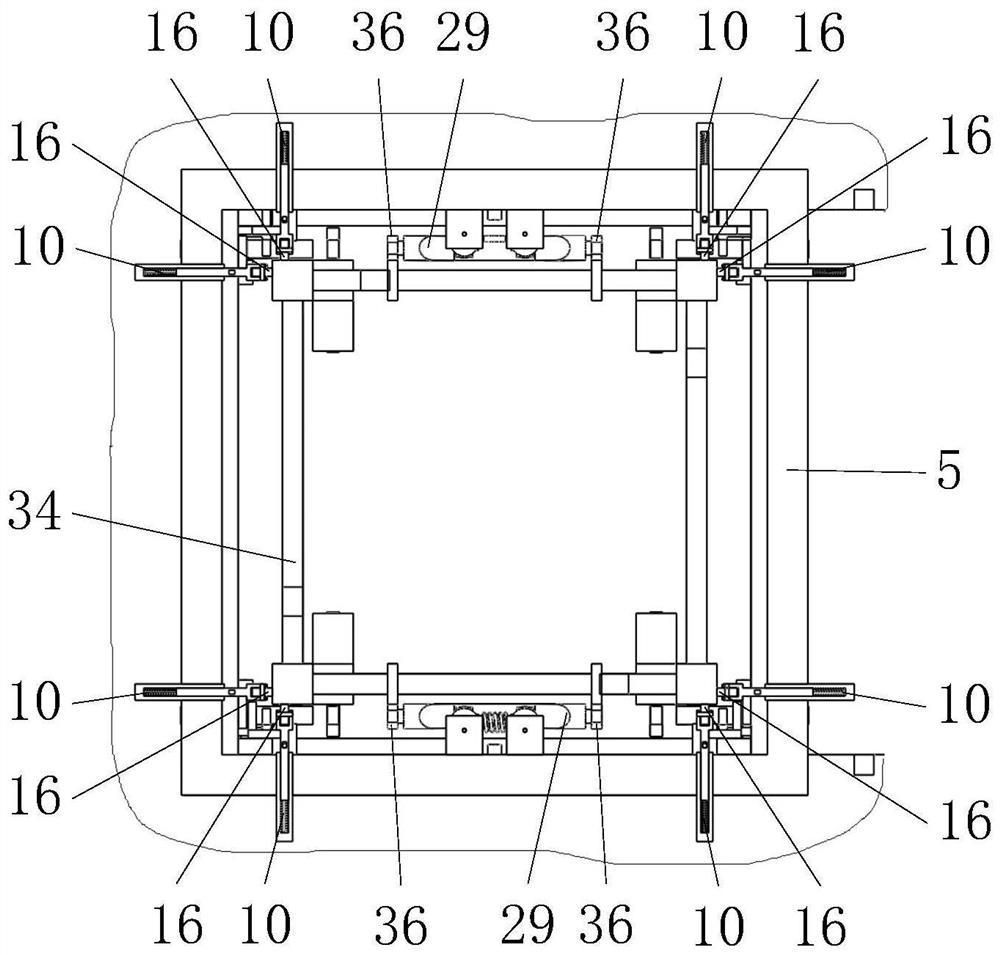
[0039] like figure 1 , 2 As shown in , 3, it includes a jacking frame 5, a hydraulic cylinder A7, a push plate 8, a jacket 10, an inner rod 12, a spring A15, a guide wheel 16, a guide seat 17, a guide wheel 16, a guide base 17, a guide wheel 16, a Rod A19, electric push rod A33, tower section 34, card plate 36, electric push rod B54, top mechanism 9, such as figure 1 , 6 As shown, two hydraulic cylinders A7 symmetrically distributed on both sides of the platform 6 and horizontally telescopic are installed on the jacking frame 5 nested in the tower section 34. The tower section 34 of the platform 6 is horizontally pulled into the push plate 8 in the jacking frame ...


PUM


Abstract

The invention belongs to the field of tower cranes, and particularly relates to an automatic jacking tower crane structure which comprises a jacking frame fixedly installed at the lower end of a tower crane rotary table, two hydraulic cylinders A, guide wheels, a tower section, an upward jacking mechanism and the like. The tail ends of the two hydraulic cylinders A are provided with push plates which are used for horizontally pulling the tower section which is hoisted to the platform through the hoisting trolley into the jacking frame; two hydraulic cylinders A can hoist a crane carriage to a tower section on a platform through a push plate to automatically pull the tower section into a jacking frame, and after the tower section is pulled into the jacking frame, an electric push rod B pushes a corresponding locking block to be inserted into a locking groove in a corresponding fixing block A to fasten and lock the tower section; and the reciprocating swing of the hydraulic cylinder B in the jacking process of the rotary table is completed by the electric push rod A, so that unmanned operation to a certain degree is realized, and effective technical support is provided for the subsequent intelligent unmanned operation of the tower crane.

Description

technical field [0001] The invention belongs to the field of tower cranes, and in particular relates to an automatic jacking tower crane structure. Background technique [0002] Tower crane, referred to as tower crane, originated in Western Europe. A rotating crane whose boom is mounted on the top of a tall tower. It has a large working space and is mainly used for the vertical and horizontal transportation of materials and the installation of building components in the construction of houses. It consists of three parts: metal structure, working mechanism and electrical system. The metal structure includes tower body, boom and base, etc. The working mechanism has four parts: lifting, luffing, turning and walking. [0003] When the tower crane is in use, it needs a jacking device to lift and heighten it. During the operation, workers are required to perform auxiliary operations such as lifting the inner front of the tower section and fixing with bolts on the jacking platf...

Claims


Application Information

Patent Timeline
Patent Type & Authority Applications(China)
IPC IPC(8): B66C23/28
CPCB66C23/286
Inventor 柳海龙罗斌飞晏勇斌陈东标叶南祥邓建林
Owner JIANGXI ZHONGTIAN INTELLIGENT EQUIP CO LTD
Why Eureka
Try Eureka