Standard knot lead-in device for self-lifting tower crane

A technology of introducing devices and standard sections, applied in the direction of cranes, etc., can solve problems such as low efficiency of lifting operations, and achieve the effect of continuous lifting operations, low cost, and improved lifting efficiency.

Inactive Publication Date: 2016-12-07
KERUN ELECTRO MECHANICAL ENG
View PDF8 Cites 0 Cited by
  • Summary
  • Abstract
  • Description
  • Claims
  • Application Information

AI Technical Summary

Problems solved by technology

Because of this, the efficiency of the jacking operation in the process of heightening the tower body is low, accounting for about one-third of the entire standard section addition time

Method used


Image

  • Standard knot lead-in device for self-lifting tower crane
  • Standard knot lead-in device for self-lifting tower crane
  • Standard knot lead-in device for self-lifting tower crane

Examples


Embodiment Construction

[0027] The present invention will be further described below in conjunction with example (accompanying drawing):

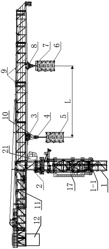
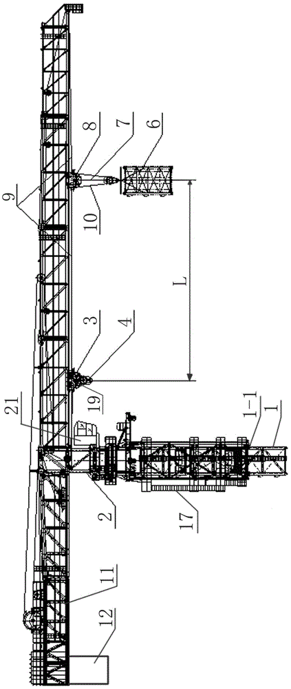
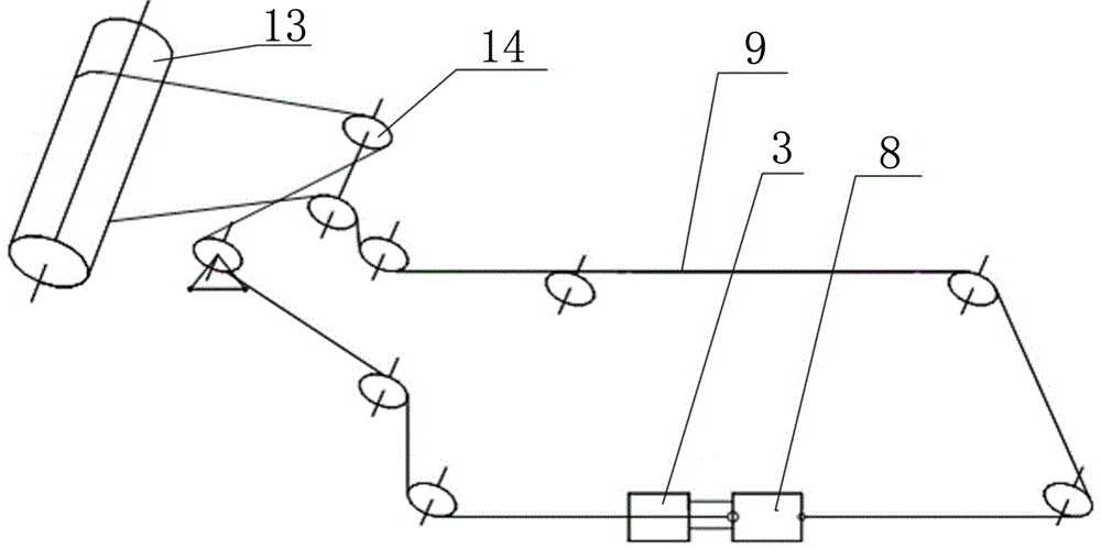
[0028] Such as figure 1 , 2 As shown, the self-elevating tower crane standard section introduction device of the present invention includes a top support 2 located at the upper end of the tower body 1, a boom 11 mounted on the upper end of the top support 2 in a hinged manner, and sleeved on the lower end of the top support 2 The peripheral sleeve frame 17 between the upper end of the tower body 1, the front and rear trolleys 8, 3 installed on the bottom guide rail of the boom 11, and the front fixed pulley 7-1 and the front movable pulley 7-2 installed on the front trolley 8 The formed front pulley block 7 is installed on the rear trolley 3 and is composed of the rear fixed pulley 4-1 and the rear movable pulley 4-2; wherein, in the inner cavity of the peripheral sleeve frame 17 and located on the top seat 2 and the space between the two adjacent ends of the to...


PUM


Abstract

The invention discloses a standard knot lead-in device for a self-lifting tower crane. The standard knot lead-in device comprises a top bearing base located at the upper end of a tower body, a cargo boom installed at the upper end of the top bearing base in a hinged mode, a peripheral sleeving frame installed between the lower end of the top bearing base and the upper end of the tower body in a sleeved mode, a front trolley, a rear trolley, a front pulley set and a rear pulley set, wherein the front trolley and the rear trolley are installed in the positions, at the bottom of the cargo boom, of a guide rail; the front pulley set is installed on the front trolley and composed of a front fixed pulley and a front movable pulley; and the rear pulley set is installed on the rear trolley and composed of a rear fixed pulley and a rear movable pulley. A space which is formed in an inner cavity of the peripheral sleeving frame and located between the two adjacent ends of the top bearing base and the tower body is an installation position of a to-be-led-in standard knot. The front and rear movable pulleys as well as the corresponding front and rear fixed pulleys are all provided with stand-by pin shaft holes. According to the standard knot lead-in device for the self-lifting tower crane, another equipment does not need to be arranged in the heightening process of the tower body, connection parts between the tower body and the top bearing base do not need to be disassembled and assembled repeatedly, continuous jacking operation is achieved, and the jacking efficiency is greatly improved; and meanwhile balance of the cargo boom of the tower crane is considered.

Description

technical field [0001] The invention relates to the technical field of hoisting machinery, in particular to a standard joint introduction device for a jacking operation of a self-elevating tower crane. Background technique [0002] With the popularization of high-rise buildings, in order to meet the needs of the corresponding construction height, construction machinery generally adopts a self-jacking method to increase the height of the tower body of the tower crane. In order to reduce the bending moment of the tower crane during jacking, it is generally necessary to adjust the balance between the boom of the tower crane and the top bearing: that is, the center of gravity of the upper structure should be basically located near the position of the top bearing. Generally, the flat arm tower crane uses its own hook to hoist the standard section when introducing the standard section, so that a set of introduction mechanism can be saved. However, when using its own hook to intro...

Claims


Application Information

Patent Timeline
Patent Type & Authority Applications(China)
IPC IPC(8): B66C23/34
CPCB66C23/344
Inventor 赵伟星胡水根李太周
Owner KERUN ELECTRO MECHANICAL ENG
Why Eureka
Try Eureka