
Charging monitoring systems

a charging monitoring and charging system technology, applied in the direction of testing electric installations on the road, transportation and packaging, instruments, etc., can solve the problems of inability to detect small fluctuations in voltage, inability to accurately or relatively and inability to accurately detect overcharge conditions. , to achieve the effect of improving the accuracy of the vehicular voltage monitoring system

Inactive Publication Date: 2006-05-02
RYNO RONALD A +1
View PDF10 Cites 84 Cited by
  • Summary
  • Abstract
  • Description
  • Claims
  • Application Information

AI Technical Summary

Benefits of technology

[0014]It is a further object and feature of the present invention to provide such a system and method, permitting electronic component calibration to provide improved monitoring accuracy.
[0015]It is a further object and feature of the present invention to provide such a system that permits precise calibration of system components.
[0030]In accordance with another preferred embodiment hereof, this invention provides a method relating to improving the accuracy of a vehicular voltage monitoring system comprising the steps of: ascertaining at least one baseline operational characteristic of such vehicular voltage monitoring system by operational testing of such voltage monitoring system; selecting at least one target operational characteristic of such vehicular voltage monitoring system; and adjusting such at least one baseline operational characteristic of such vehicular voltage monitoring system to match such at least one target operational characteristic; wherein such adjusting at least includes altering at least one software component of such vehicular voltage monitoring system.

Problems solved by technology

Both overcharge and undercharge conditions are potentially damaging to electrical system components, to the point of rendering the host vehicle inoperable.
Existing systems to meter the voltage status of vehicular electrical systems have been either inexpensive and acutely inaccurate or relatively accurate but exceedingly expensive and complex to implement.
These small fluctuations in voltage are presently undetectable by inexpensive charge warning indicators.

Method used


Image

  • Charging monitoring systems
  • Charging monitoring systems
  • Charging monitoring systems

Examples


Embodiment Construction

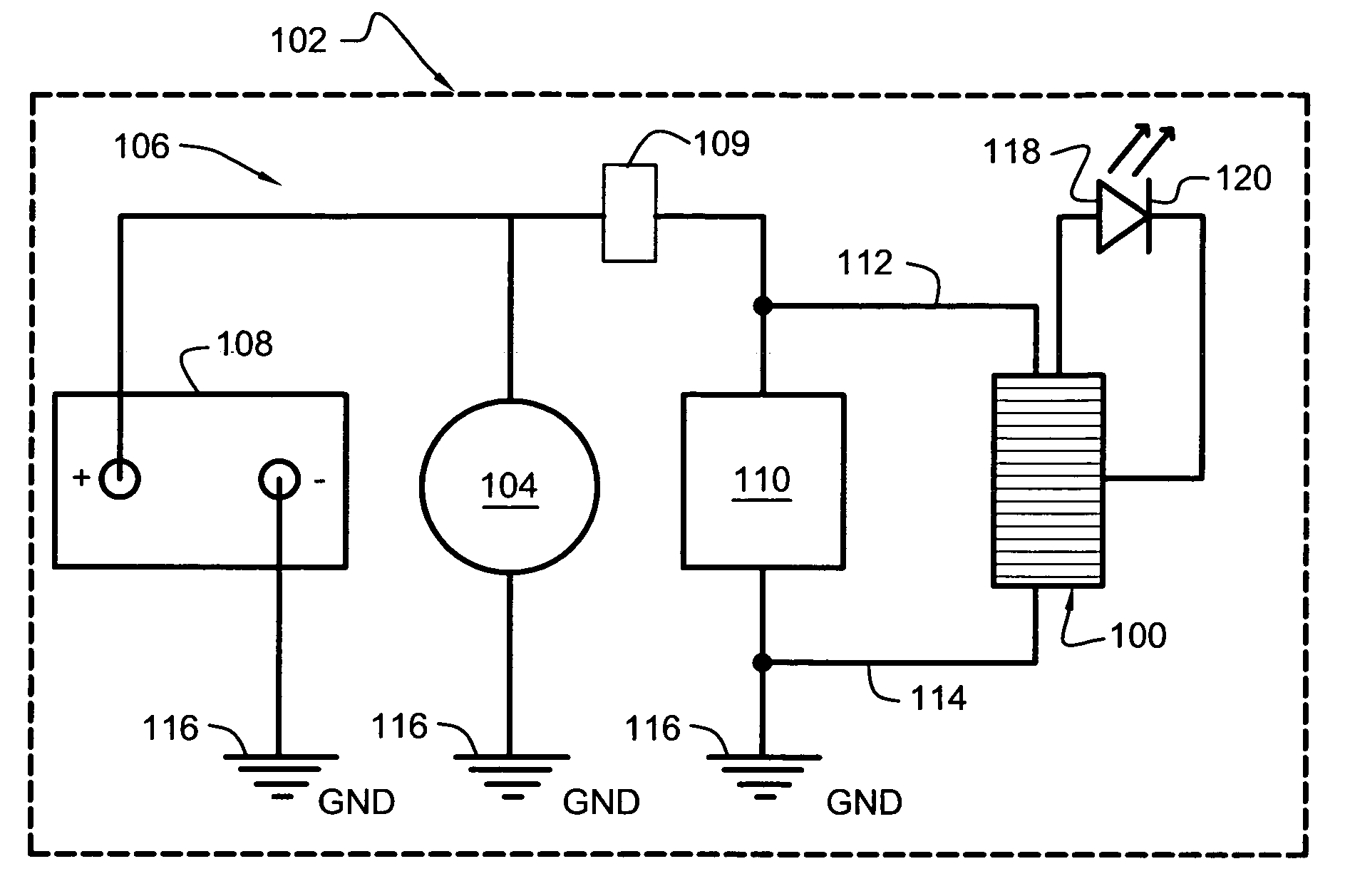
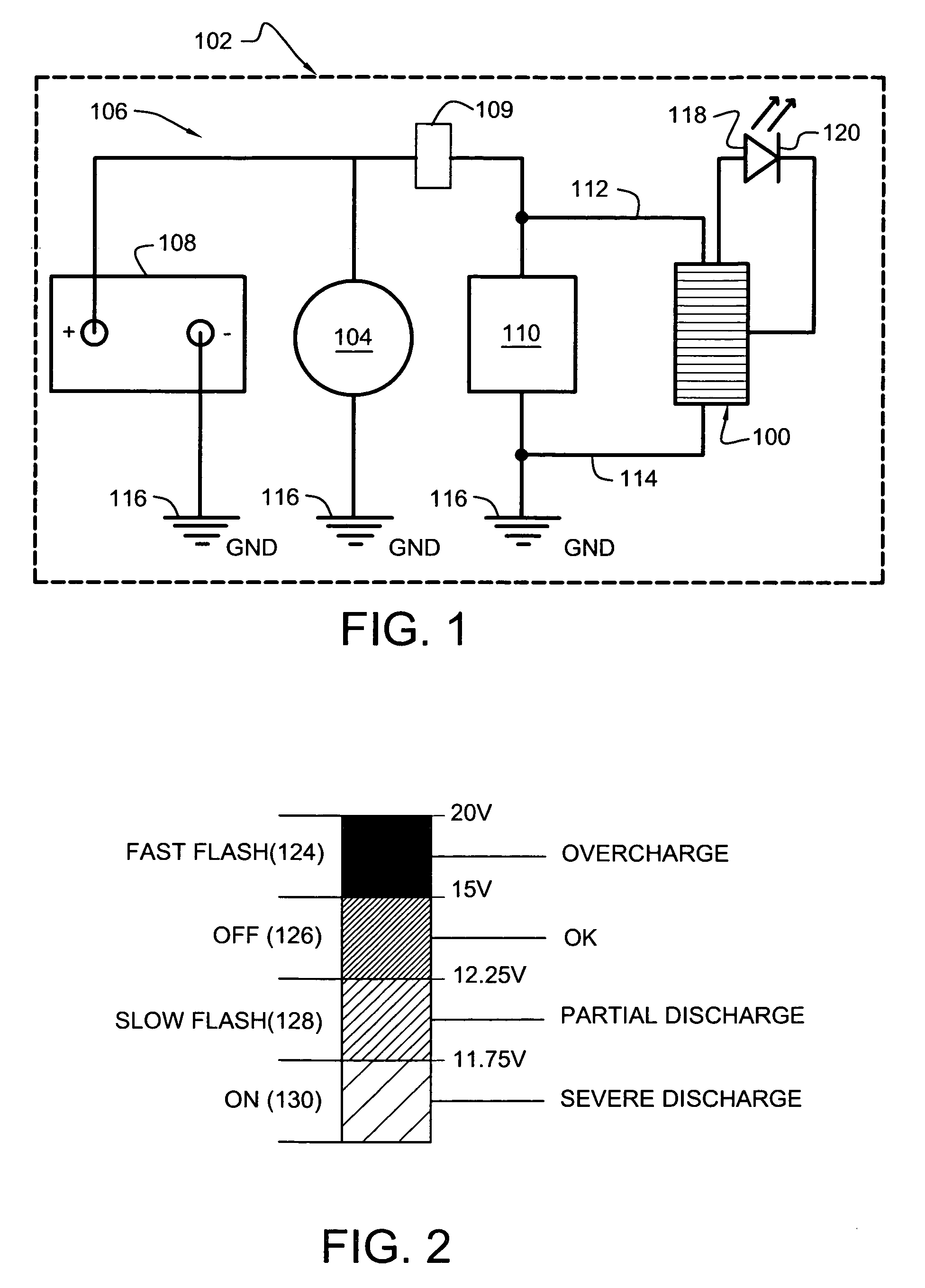
[0053]Referring now to the drawings, FIG. 1 illustrates, in block diagram form, typical host vehicle 102 utilizing monitoring system 100 to continuously monitor the operational status of electrical system 106. For the purposes of best following the teachings of the present disclosure, it is assumed that electrical system 106 resides within a motorized host vehicle, such as, for example, a motorcycle, car, or boat, and that the nominal operating voltage of electrical system 106 is twelve (12) volts DC.

[0054]In the diagrammatic example of FIG. 1, electrical system 106 typically comprises secondary storage battery 108, alternator 104, ignition control device 109 and electrical load 110, as shown. Electrical load 110 typically comprises such diverse current-drawing devices as a starter motor, headlights, gauges, fans and similar electrical equipment. During normal operation, alternator 104 charges battery 108 when the engine of host vehicle 102 is operating. To charge battery 108, alter...


PUM


Abstract

An electronic system for the continuous monitoring of voltage charge within the electrical system of a motor vehicle having an electrical generation source and a secondary electrochemical cell or battery. The system comprises a programmable in-vehicle monitor having a flashing LED indicator that alerts the vehicle operator of the condition of the electrical system. An example of the invention comprises a plug-in housing for use in a vehicle accessory-power-socket. Additionally, a method of market distribution is disclosed.

Description

CROSS-REFERENCE TO RELATED APPLICATION[0001]The present application is related to and claims priority from prior provisional application Ser. No. 60 / 517,150, filed Nov. 3, 2003, entitled “CHARGING MONITORING SYSTEM”, the contents of which are incorporated herein by this reference and are not admitted to be prior art with respect to the present invention by the mention in this cross-reference section.BACKGROUND[0002]This invention relates to providing a system for improved monitoring of a vehicle electrical system. More specifically, this invention relates to the continuous monitoring of voltage charge within the electrical system of a motor vehicle having an electrical generation source and a secondary, typically electrochemical, cell or battery.[0003]The lead-acid storage battery has proven to be an efficient and reliable electrochemical energy source since its commercial introduction about 125 years ago. In addition to being a highly efficient energy source, lead-acid storage batt...

Claims


Application Information

Patent Timeline
Patent Type & Authority Patents(United States)
IPC IPC(8): G01R31/36
CPCG01R19/16542H02J7/1461G01R31/3648G01R31/005Y02T10/7005G01R31/3689G01R31/371Y02T10/70H02J7/14H02J7/0049
Inventor RYNO, RONALD A.RYNO, SHIRLEE M.
Owner RYNO RONALD A
Learn More