Exposure apparatus
a technology for exposure apparatus and coolant, which is applied in the field of exposure apparatus, can solve the problems of increasing the cost of an exposure apparatus which requires a large amount of coolant, and the difficulty of ensuring the flow rate of the higher flow rate, so as to suppress metal rust and compactness, and without adversely affecting the cleanness of the semiconductor factory
- Summary
- Abstract
- Description
- Claims
- Application Information
AI Technical Summary
Benefits of technology
Problems solved by technology
Method used
Image
Examples
first embodiment
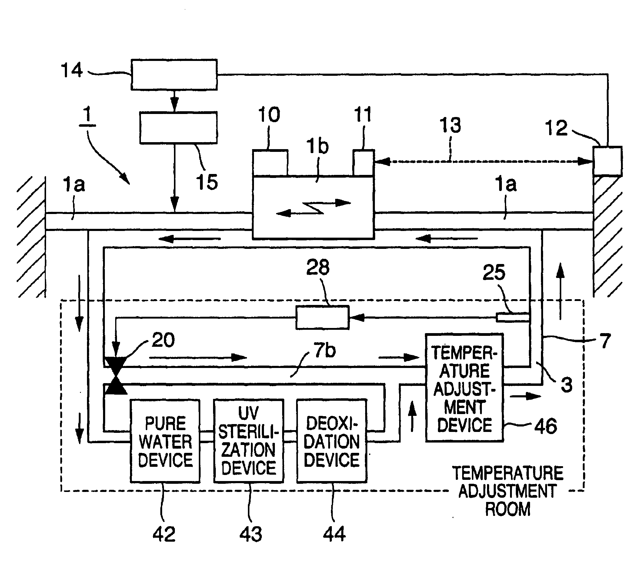
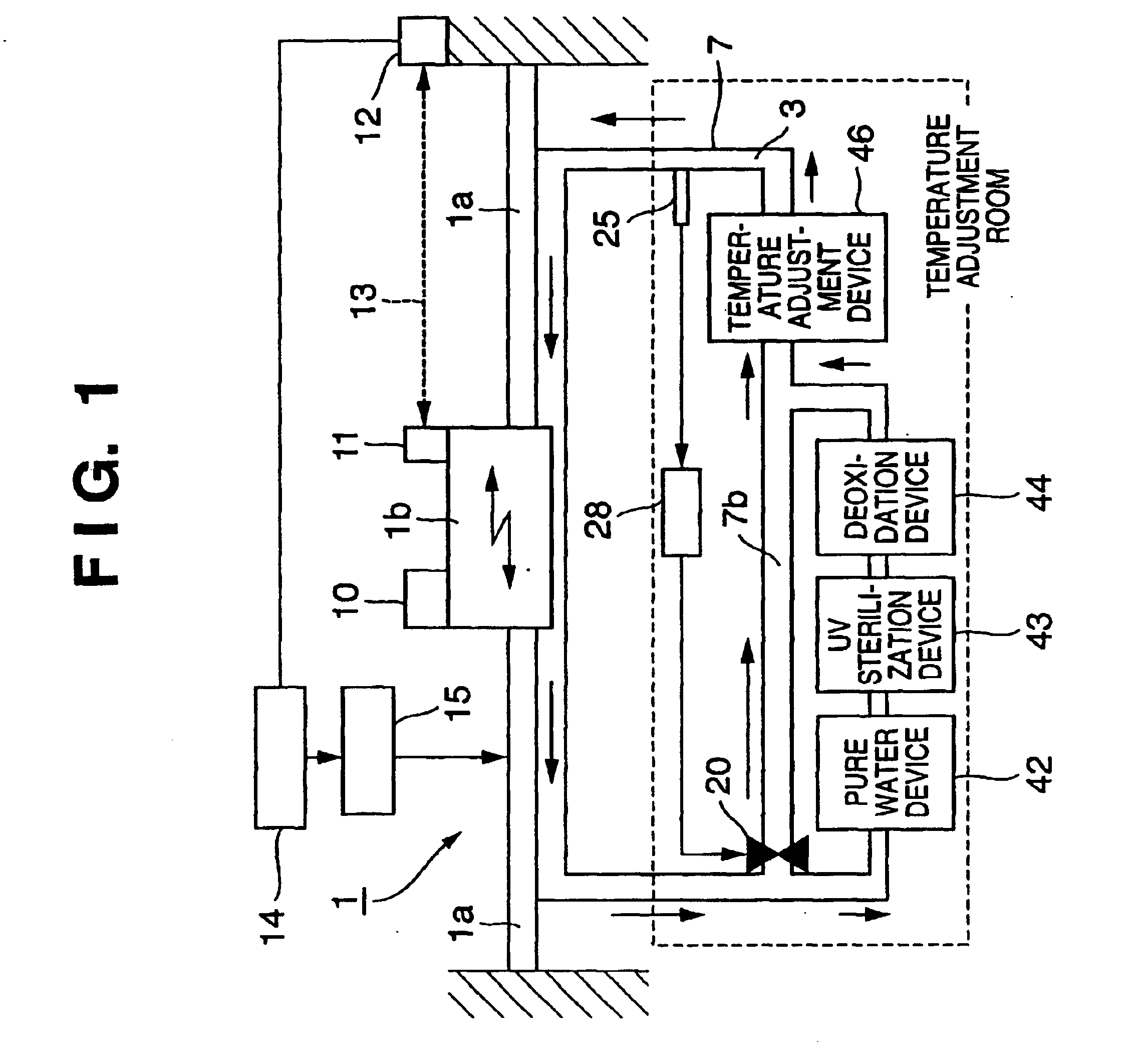
[0058]Outputs from the water quality sensor 25 and flow rate sensor 26 are sent to the valve controller 28, which controls opening / closing of supply and exhaust valves 16 and 18 and controls the water quality and flow rate of the circulating pure water 3. An output from the temperature sensor 27 is sent to a controller 14, which controls the temperature adjustment device 46 via a cooling control means 4 and controls the temperature or flow rate of the pure water 3. The flow rate sensor 26, temperature sensor 27, and filter 48 can also be applied to the first embodiment shown in FIG. 1.
[0059]It is generally known that deoxidation processing performed for a coolant by a deoxidation device prevents rust of metal in contact with the coolant. From the reaction formula describing rusting of a metal:
Fe+(1 / 2)O2+7H2O=Fe(H2O)62+2OH
necessary conditions of rusting metal are the following three: ① water exists on the surface of iron, ② oxygen is dissolved in water, and ③ ionization of iron and r...
second embodiment
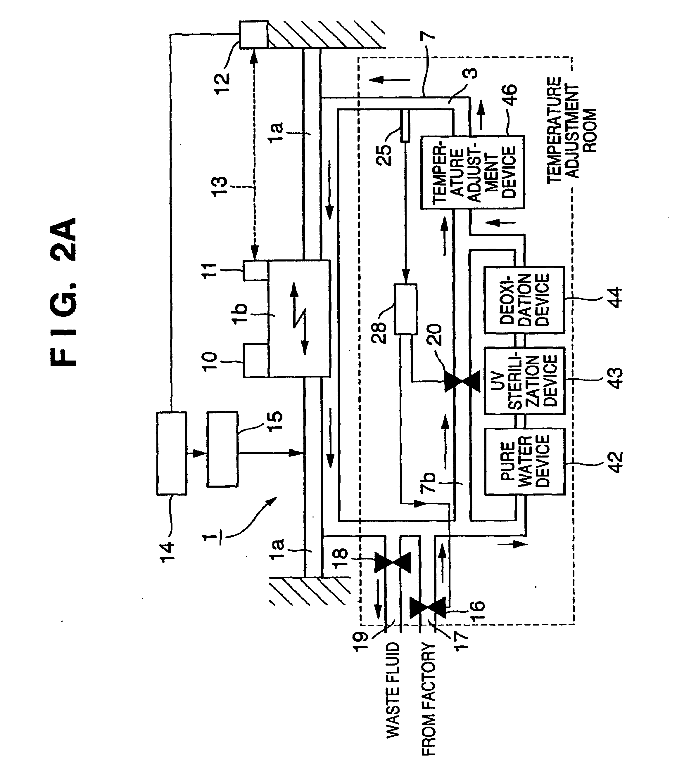
[0071]To supply high-level pure water from the factory when the water quality reaches a predetermined criterion or less, the flow rate of pure water supplied from the factory can be controlled by controlling the opening degree of a flow rate sensor 26 by a valve controller 28 on the basis of the water quality detection result of a water quality sensor 25 which detects the water quality in a channel 7. The water quality sensor 25 detects the purity, oxygen concentration, and the like. The purity is detected by measuring the conductivity of pure water. The second embodiment adopts a bypass valve 20 which opens / closes a bypass-side channel 7b which does not pass through the deoxidation device 44. The flow rate of pure water flowing through the pure water device 42, UV sterilization device 43, and deoxidation device 44 can also be controlled by controlling the bypass valve 20 by the valve controller 28 on the basis of the water quality detection result of the water quality sensor 25. In...
third embodiment
[0072]FIG. 2B is a view showing an example of a cooling system according to the present invention. In FIG. 2B, the same reference numerals as in FIG. 8 denote the same parts.
[0073]Implementation of the cooling systems shown in the structural views of FIGS. 1 and 2A requires a large-size pure water device 42, UV sterilization device (UV filter) 43, and deoxidation device 44 in order to maintain the water quality of circulating pure water. The results of further examination revealed that simply circulating pure water in the arrangement as shown in FIG. 1 or 2A requires an apparatus almost twice as large as a conventional one. In order to minimize the sizes of various devices which maintain the water quality of pure water used for temperature adjustment, pure water is supplied from a semiconductor factory which has large amounts of high-level pure water and deaerated pure water, thereby downsizing the apparatus. That is, the use of pure water with high water quality can decrease the bu...
PUM
| Property | Measurement | Unit |
|---|---|---|
| resistivity | aaaaa | aaaaa |
| distance | aaaaa | aaaaa |
| temperature | aaaaa | aaaaa |
Abstract
Description
Claims
Application Information
 - R&D
- Intellectual Property
- Life Sciences
- Materials
- Tech Scout
- Unparalleled Data Quality
- Higher Quality Content
- 60% Fewer Hallucinations
Browse by: Latest US Patents, China's latest patents, Technical Efficacy Thesaurus, Application Domain, Technology Topic, Popular Technical Reports.
© 2025 PatSnap. All rights reserved.Legal|Privacy policy|Modern Slavery Act Transparency Statement|Sitemap|About US| Contact US: help@patsnap.com


