
Color gradient paths

a color gradient and path technology, applied in the field of computer graphics, can solve the problems of complex gradients, heavy user burden, and more powerful gradient meshes, and achieve the effects of smooth color gradient generation, smooth color gradient variation, and quick and easy creation of rich and smooth color gradients

Inactive Publication Date: 2006-05-02
MICROSOFT TECH LICENSING LLC
View PDF11 Cites 17 Cited by
  • Summary
  • Abstract
  • Description
  • Claims
  • Application Information

AI Technical Summary

Benefits of technology

The present invention provides a system and method for creating smooth color gradients using techniques from geometric surface modeling. This system and method allow designers to easily create complex gradients with smoothly varying colors and scales. The resulting color gradients can be quickly and efficiently drawn using computer graphics hardware. The invention also allows for compact and scalable graphic representations of color gradients that can be transmitted across computer networks. Additionally, color gradients generated in accordance with the invention can be built on top of vector and bitmap / raster graphics, providing a richer and easier editing experience. Overall, the invention offers a more visually rich and efficient way to create color gradients.

Problems solved by technology

The linear gradient is the most basic gradient of all and is typically not complex enough for advanced effects.
The mesh gradient is more advanced than both linear and radial gradients; however, complex mesh gradients put a heavy burden on the users, as they can only be achieved by specifying the positions and colors of many control points.
A gradient mesh is more powerful, but is more difficult for designers to use.
It is also difficult to define a mesh gradient to fill a non-rectangular region, since Bézier surfaces are typically defined using quadrilateral meshes.
Achieving a desired appearance is also time-consuming and non-intuitive, since more complicated effects generally require the user to individually move and color many control points.

Method used


Image

  • Color gradient paths
  • Color gradient paths
  • Color gradient paths

Examples


Embodiment Construction

[0034]The present invention is now described with reference to the drawings, wherein like reference numerals are used to refer to like elements throughout. In the following description, for purposes of explanation, numerous specific details are set forth in order to provide a thorough understanding of the present invention. It may be evident, however, that the present invention may be practiced without these specific details. In other instances, well-known structures and devices are shown in block diagram form in order to facilitate describing the present invention.

[0035]As used in this application, the term “computer component” is intended to refer to a computer-related entity, either hardware, a combination of hardware and software, software, or software in execution. For example, a computer component may be, but is not limited to being, a process running on a processor, a processor, an object, an executable, a thread of execution, a program, and / or a computer. By way of illustrat...


PUM


Abstract

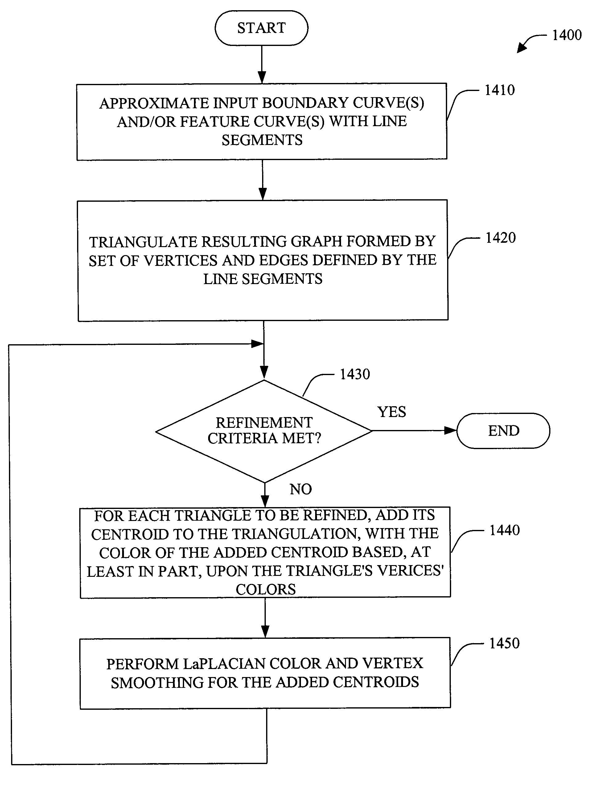
A system and method for generating color gradients is provided. The system generates color gradients using techniques from geometric surface modeling. The system and method of the present invention allow designers to specify very complex gradients in a simple way. The system can employ, for example, a vector-based interpolation method and / or a pixel-based partial differential equation (PDE) interpolation methods to facilitate generation of the color gradients. In one example, input boundary curves and / or feature curves are approximated by line segments, which are then utilized to generate a triangulation approximating a smooth color gradient.

Description

CROSS-REFERENCE TO RELATED APPLICATIONS[0001]This application is a continuation-in-part of U.S. application Ser. No. 10 / 417,937 which was filed on Apr. 16, 2003 now U.S. Pat. No. 6,856,705 entitled IMAGE BLENDING BY GUIDED INTERPOLATION, which claims priority to U.S. Provisional Application Ser. No. 60 / 450,078 entitled IMAGE BLENDING BY GUIDED INTERPOLATION filed on Feb. 25, 2003, the entire disclosures of which are incorporated herein by reference.TECHNICAL FIELD[0002]The present invention relates generally to computer graphics, and, more particularly to a system and method to facilitate smooth color gradient(s) by employing color gradient path(s).BACKGROUND OF THE INVENTION[0003]Many computer paint and drawing programs allow a user to fill an area with a single and / or multiple colors. In the case of multiple colors, computer paint programs can automatically blend between the colors specified. This smooth blending between colors produces a color gradient. Conventional types of colo...

Claims


Application Information

Patent Timeline
Patent Type & Authority Patents(United States)
IPC IPC(8): G09G5/08G09G5/02G06T1/00G06T5/00G06T11/00G06T11/40H04N1/46H04N1/60
CPCG06T11/001G06T11/40
Inventor GANGNET, MICHEL J.KALLAY, MICHAELWU, ANDREW Y.STOLLNITZ, ERIC J.STRAWN, DEVON L.LOUNSBERY, JOHN MICHAELPEREZ, PATRICK
Owner MICROSOFT TECH LICENSING LLC
Learn More