
Cell, cell production method, welded article production method and pedestal

Inactive Publication Date: 2006-05-02
MURATA MFG CO LTD
View PDF33 Cites 32 Cited by
  • Summary
  • Abstract
  • Description
  • Claims
  • Application Information

AI Technical Summary

Benefits of technology

[0018]It is another object of the invention to provide a method of manufacturing a weldment in which two or more objects being welded which

Problems solved by technology

However, there is a problem that poor welding occurs in the case of the electric resistance welding between the above electrode and the metal plate.
The first reason for the difficulty of the electric resistance welding is the difference between aluminum and nickel melting points.
Accordingly, the dissolved metal is spilt out, aluminum evaporates and scatters around violently after the aluminum plate of the weld part reaches the boiling point, or the like phenomenon occurs, which causes generation of a hole in the part and poor welding without the sure welding.
However, since the nickel base alloy on the metal plate surface does not fuse, the normal nugget of both the nickel base alloy and the aluminum base alloy is not formed, only the trace of the aluminum base alloy melting is left on the cross section surface after the welding, and the poor welding of the unsure welding occurs.
However, such a condition setup unavoidably becomes very delicate, since the difference between the metal of the metal plate such as the nickel base alloy and metal of the electrode such as the aluminum base alloy melting points, is too large.
Moreover, the tip of the electrode pole is degraded and deformed as the welding is continued, so it is very difficult to continuously maintain the setup of the above preferable delicate welding conditions in the actual mass production process, and therefore it is difficult to reduce the occurrence rate of the poor welding.
However, if the nickel plate composes the positive electrode terminal strip, the nickel plate may react electrically in the inside of the battery and dissolve, and thus it is not preferable.
As described above, it is technically difficult to perform the electric resistance welding of the thin aluminum plate and the nickel plate, and particularly, the welding of the positive electrode terminal strip and a wiring board is conventionally performed by the ultrasonic welding.
However, there have been the following problems in the ultrasonic welding.
First, the setting ranges of oscillating strength and amplitude time of the ultrasonic welding are small, and it is difficult to maintain the optimum conditions of the welding.
Secondly, it is difficult to stabilize the welding strength, and the poor welding may occur at a certain rate in the mass production process for manufacturing the products in large quantities.
Because, in the ultrasonic welding, only a very thin alloy layer is produced at the interface between the electrode and the metal plate, both are in the weakly connecting state only on the surface in many cases due to increasing the

Method used


Image

  • Cell, cell production method, welded article production method and pedestal
  • Cell, cell production method, welded article production method and pedestal
  • Cell, cell production method, welded article production method and pedestal

Examples


first embodiment

[First Embodiment]

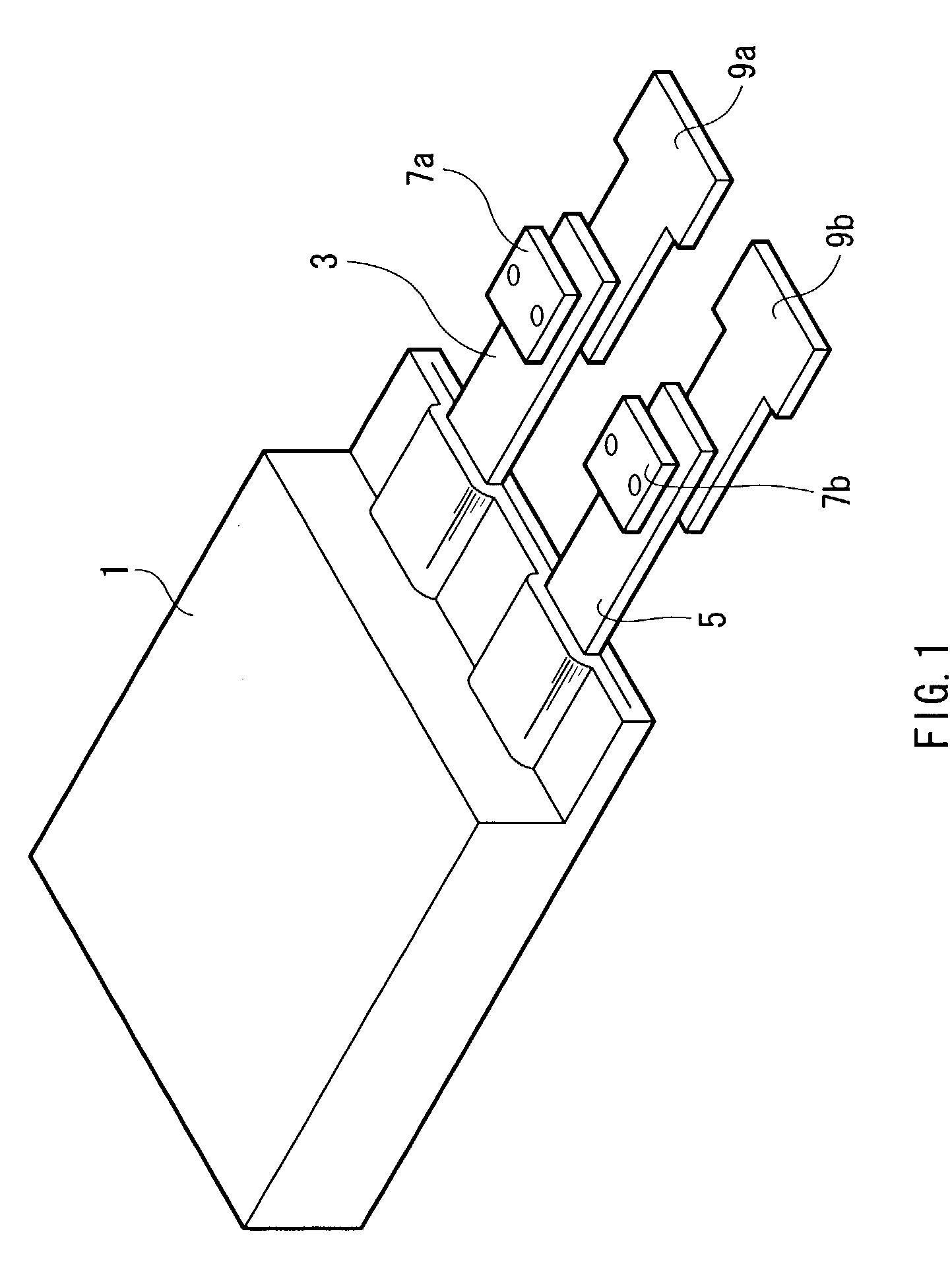
[0069]FIG. 1 shows a schematic structure of a lithium ion secondary battery according to a first embodiment of the invention.

[0070]The lithium ion secondary battery has a principal part constituting of a secondary battery cell 1, a pole / terminal of positive electrode 3, a pole / terminal of negative electrode 5, an upper metal plate 7a and a lower metal plate 9a on the positive pole / terminal, and an upper metal plate 7b and a lower metal plate 9b on the negative pole / terminal. And, in fact, the principal part with these elements is covered with a coating material such as an aluminum laminate film, while the coating material have been left out of the illustration in order to show an internal structure clearly here. Moreover, for convenience, the metal plates positioned on the upper side and lower side on the basis of the vertical direction in the figure, shall be here called upper metal plates 7a and 7b and lower metal plates 9a and 9b respectively, while this is not ...

second embodiment

[Second Embodiment]

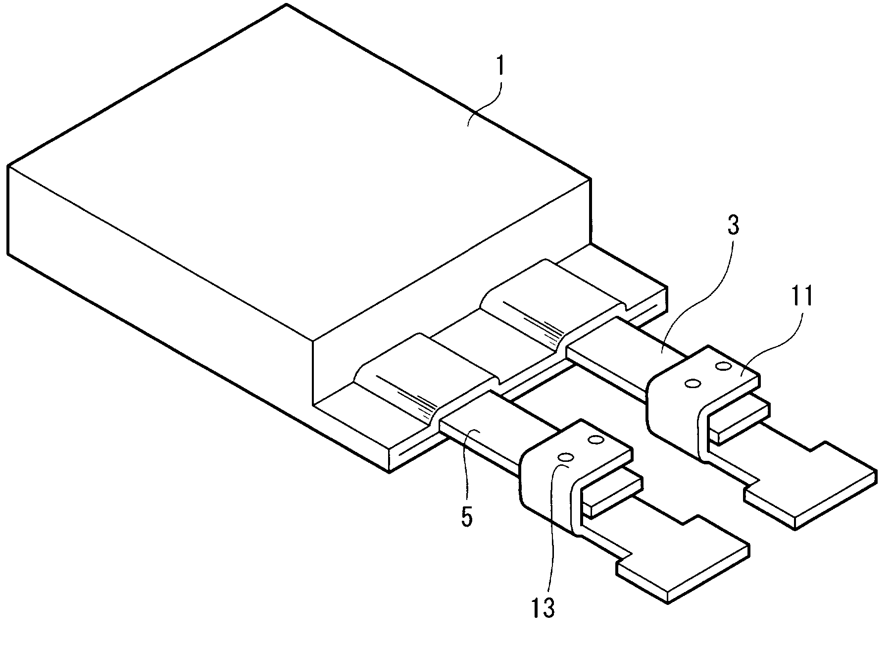
[0087]FIG. 4 shows a schematic structure of a lithium ion secondary battery according to a second embodiment of the invention. And in the embodiment, the same compositions as the first embodiment are marked in the same signs, the explanations thereof are omitted and only different points will be explained. The third embodiment and the following embodiments can also be described in the same way.

[0088]The lithium ion secondary battery has a principal part constituting of a secondary battery cell 1, a pole / terminal of positive electrode 3, a pole / terminal of negative electrode 5, a metal plate 11 on the positive pole / terminal, and a metal plate 13 on the negative pole / terminal. Among these components, the secondary battery cell 1, the pole / terminal of positive electrode 3, and the pole / terminal of negative electrode 5 are the same as those of the first embodiment.

[0089]Each of the metal plate 11 on the positive pole / terminal and the metal plate 13 on the negative pol...

third embodiment

[Third Embodiment]

[0099]FIG. 6 shows a schematic structure of a lithium ion secondary battery according to a third embodiment of the invention.

[0100]The lithium ion secondary battery has a principal part constituting of the secondary battery cell 1, a pole / terminal of positive electrode 3 with a tip portion having a slit-like cut, a pole / terminal of negative electrode 5 similarly with a tip portion having a slit-like cut, a metal plate 15 on the positive pole / terminal where a tip portion thereof is bent and converted into a horseshoe shape and an upper board thereof has a slit-like cut, and a metal plate 17 on the negative pole / terminal where a tip portion thereof is similarly bent and converted into a horseshoe shape and an upper board thereof has a slit-like cut.

[0101]In the steps of welding the pole / terminal of positive electrode 3 and the metal plate 15 with the electric resistance welding process, and welding the pole / terminal of negative electrode 5 and the metal plate 17 with...


PUM

PropertyMeasurementUnit
Lengthaaaaaaaaaa
Lengthaaaaaaaaaa
Lengthaaaaaaaaaa

Abstract

A metal plate and an electrode in a polymer lithium ion secondary battery or the like are welded certainly, and it is accomplished to further improve the reliability and the durability thereof. Each of an upper metal plate (7a) and a lower metal plate (9a) on the positive pole/terminal is welded to a pole/terminal of positive electrode (3) so that the pole/terminal of positive electrode (3) may be sandwiched from each of the upper and lower sides. Moreover, each of an upper metal plate (7b) and a lower metal plate (9b) on the negative pole/terminal is welded to a pole/terminal of negative electrode (5) so that the pole/terminal of negative electrode (5) may be sandwiched from each of the upper and lower sides. This eliminates occurrence of poor welding in the electric resistance welding.

Description

TECHNICAL FIELD[0001]The present invention relates to a battery having a structure with a metal plate welded to an electrode, a method of manufacturing the same comprising the welding step, a method of manufacturing weldment, and pedestal.BACKGROUND OF THE INVENTION[0002]Lithium ion secondary batteries have been used in recent years as a power supply with ability of charge and discharge of electricity which is incorporated in cellular phones or portable electric devices. Moreover, for example, batteries using a solid-like unfluidized electrolyte as the electrolyte without danger of liquid leakage are also known. There are various outside forms of such a lithium ion secondary battery, and the batteries, generally used for notebook type or pocketbook type portable electric devices and cellular phones, are flat type in many cases. In such a flat type lithium ion secondary battery, in order to produce electric current continuity between a main body of a secondary battery cell and the ex...

Claims


Application Information

Patent Timeline
IPC IPC(8): H01M4/02B23K11/11B23K11/18B23K11/20B23K35/00H01M10/04H01M10/052H01M10/0525H01M10/0565H01M10/36H01M50/176H01M50/50H01M50/529H01M50/55H01M50/553H01M50/562
CPCB23K11/11B23K35/268B23K35/3006B23K35/302H01M2/20H01M2/22H01M2/26H01M2/30H01M2/34H01M10/052H01M10/0525H01M10/0565H01M10/38B23K35/025Y10T29/49114B23K2201/38B23K2203/18H01M10/36Y02E60/122B23K2101/38B23K2103/10B23K2103/18B23K2103/20B23K2103/26Y02E60/10H01M50/50H01M50/528Y02P70/50H01M50/562H01M50/55H01M50/553H01M50/176
Inventor KIKUCHI, KIYOSHIFUKUTA, KOICHISATO, BUNYASASAKI, SHUJIANZAI, CHIAKIANZAI, HIROSHI
Owner MURATA MFG CO LTD
Learn More