
Method and apparatus to control an exhaust gas sensor to a predetermined termperature

Inactive Publication Date: 2006-05-02
DELPHI TECH IP LTD
View PDF54 Cites 32 Cited by
  • Summary
  • Abstract
  • Description
  • Claims
  • Application Information

AI Technical Summary

Benefits of technology

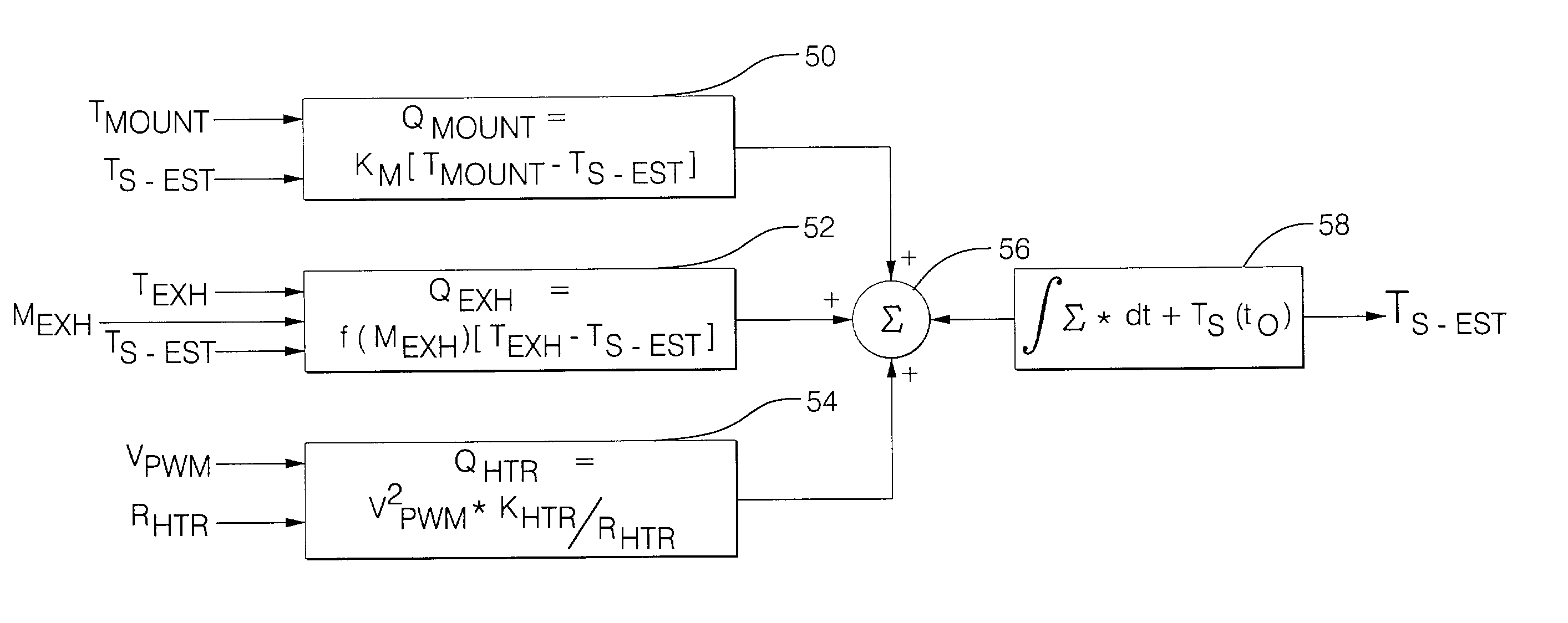
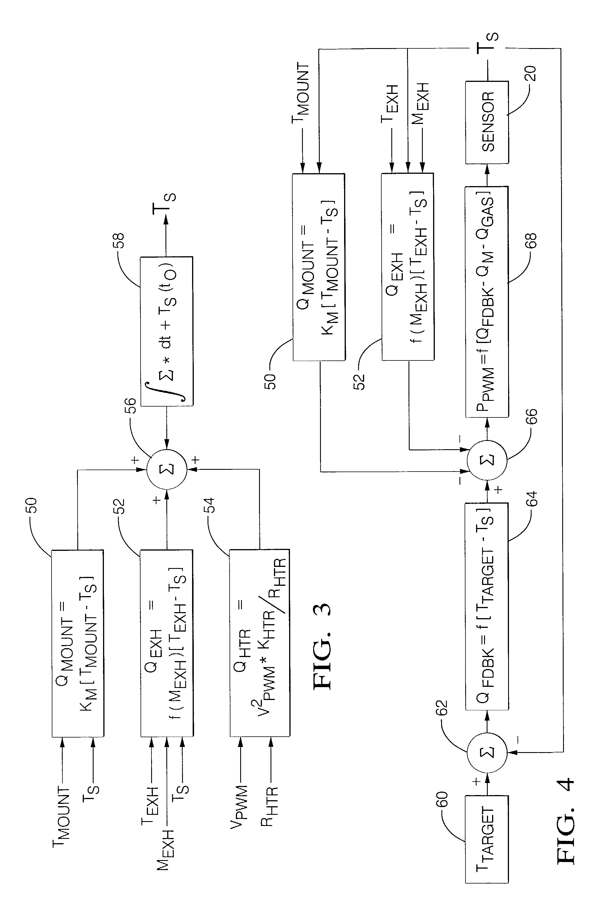
[0015]The present invention is an improvement over conventional gas sensor heating element control systems in that it provides a method and apparatus to determine the sensor operating temperature based upon an electrical heat input to the sensor, the gas feedstream temperature, and the mounting structure of the sensor. The method and apparatus control the gas sensor to a target operating temperature, using a control strategy and control system. The present invention relies upon a heating model, and feedback and model-based feedforward control systems to achieve and maintain the sensor at the target operating temperature. This includes providing a gas sensor with a controllable heating element which is preferably a resistive device. The gas sensor is operable to measure a parameter of the gas feedstream. The control strategy employs a control system for the heating element that is based upon the target operating temperature, the temperature of the heating element, and an effect of the feedstream and mounting structure on the temperature of the sensor. The control strategy enables the control system to optimize the heating of a sensor during a warm-up period, but still prevent overheating of the sensor. The control strategy determines the external effects of the feedstream and mounting structure on the temperature of the sensor by employing a feedforward disturbance rejection that is based upon a determination of heat transfer from the feedstream and a sensor mounting structure.
[0016]The target operating temperature of the sensor can be a maximum operating temperature, or a steady-state operating temperature that is less than maximum, or it can be a predetermined operating temperature. When the control strategy operates at a predetermined operating temperature, it employs heating element control techniques that address the specific operating characteristics of the system. For example, a control strategy may have a goal to operate at a sensor temperature below a maximum operating temperature, in order to allow the system to be able to accommodate variations in other areas that influence the sensor operating temperature. This includes variations caused by changes in the temperature of the feedstream, or variations in system voltage levels. A control strategy may instead seek to limit the time-rate change in temperature of the sensor during a warm-up period. The desire to limit the warm-up rate can be based upon concerns for sensor durability, or concerns for changes in feedstream during the warm-up period. One such change in the feedstream occurs when the sensor is used to measure an output from a combustion process, as when the sensor is used to monitor an output from an internal combustion engine. Water is created as a byproduct of combustion and results in airborne water droplets, especially during the warm-up period. The water droplets impinge upon a sensor and cause thermal shock of the sensor element or external shield. A limit on the warm-up rate of the sensor improve the durability of the sensor by reducing a risk of thermal shock and material degradation caused by water impingement. A limit in the warm-up rate may also be based upon a need to manage electrical energy consumption in the system. The control system limits power delivered to the sensor at initial startup and other times when the system does not require the sensor to be operational.

Problems solved by technology

The water droplets impinge upon a sensor and cause thermal shock of the sensor element or external shield.

Method used


Image

  • Method and apparatus to control an exhaust gas sensor to a predetermined termperature
  • Method and apparatus to control an exhaust gas sensor to a predetermined termperature
  • Method and apparatus to control an exhaust gas sensor to a predetermined termperature

Examples


Embodiment Construction

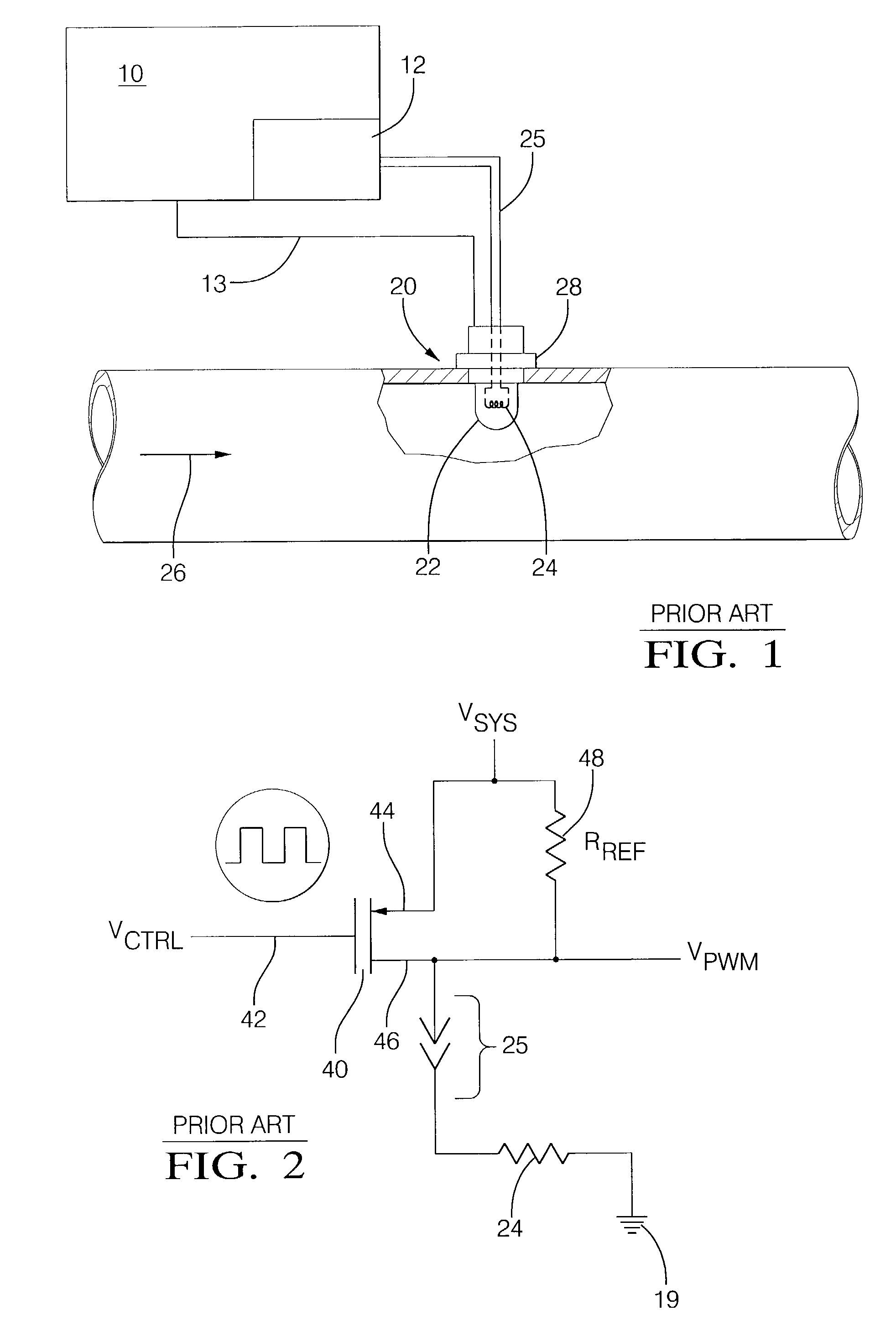
[0030]Referring now to the drawings, wherein the showings are for the purpose of illustrating an embodiment of the invention only and not for the purpose of limiting the same, FIG. 1 shows an exhaust gas sensing system controllable to a predetermined temperature which has been constructed in accordance with an embodiment of the present invention. The system includes an exhaust gas sensor 20 comprising a sensing element 22 and a controllable heating element 24 that is operably attached to a controller 10. The controller 10 has an output device 12 that is operably attached to the controllable heating element 24. There is a signal, VSEN, that is the output of the sensing element 22 and is input to the controller 10 over signal line 13. In this embodiment, the exhaust gas sensor 20 is mounted in an exhaust feedstream 26 of an internal combustion engine (not shown) that is controlled by the controller 10. The sensor is mounted in an exhaust pipe on a mounting structure 28 that can compri...


PUM


Abstract

The invention provides a control strategy and a control system to control a gas sensor to a target operating temperature. It relies upon both feedback and model-based feedforward control systems to achieve and then maintain the sensor at the target operating temperature. The mechanization includes a gas sensor with a heating element in a feedstream. The control strategy employs a control system for the heating element that is based upon the target operating temperature, the temperature of the heating element, and an effect of the feedstream and mounting structure on the temperature of the sensor. The control strategy enables the control system to optimize the heating of a sensor during warm-up and steady state operations.

Description

TECHNICAL FIELD[0001]This invention pertains generally to gas sensors, and more specifically to a control system for controlling an operating temperature of an exhaust gas sensor.BACKGROUND OF THE INVENTION[0002]Sensors are used in control systems of internal combustion engines and other combustion devices to measure operating parameters and constituents of a resulting feedstream. Sensor information is provided to a controller that can control an incoming feedstream or trigger an alarm based upon the measured parameter or constituent. For example, an exhaust gas sensor in a control system of an internal combustion engine is used to measure the parameter of air / fuel ratio. An engine controller can then use the air / fuel ratio information to control the feedstream that flows through the engine and into an aftertreatment system, such as a catalytic converter. A properly controlled gas feedstream is important for complete operation of the exhaust aftertreatment system during light-off an...

Claims


Application Information

Patent Timeline
IPC IPC(8): G01K13/00F01N3/00F02D41/00F02D41/14G01K1/08
CPCF02D41/1494G01K1/08G01K2205/04
Inventor SMITH, JAMES CRAIGMOORE, WAYNE RICHARDFOSTER, MATTHEW G.
Owner DELPHI TECH IP LTD
Learn More