
Self-pumping hydropneumatic suspension strut

a technology of hydropneumatic suspension and self-pumping, which is applied in the direction of shock absorbers, mechanical equipment, transportation and packaging, etc., can solve the problems of inability to manufacture this type of design, inability to properly operate the pump itself, and considerable work involved in the assembly of the horizontal type of suspension strut, etc., to achieve favorable design

Inactive Publication Date: 2006-05-02
ZF FRIEDRICHSHAFEN AG
View PDF8 Cites 8 Cited by
  • Summary
  • Abstract
  • Description
  • Claims
  • Application Information

AI Technical Summary

Benefits of technology

The solution simplifies the assembly process, reduces unsprung masses, and ensures proper function by allowing in-position filling and installation, preventing gas leakage into the pump space, thus enhancing manufacturing efficiency and vehicle performance.

Problems solved by technology

It is quite problematic to manufacture this type of design, however, because it must be done horizontally (FIGS. 3 and 4 of U.S. Pat. No. 6,648,309).
When the unit is to be filled with gas, the damping medium of the high-pressure chamber must be free to interchange with the damping medium of the low-pressure chamber via the open discharge bore so that the pressure can be equalized; during this process, the compressed gas may not pass from the low-pressure chamber into the pump space, for otherwise the pump itself will not be able to operate properly.
In addition, the assembly of a suspension strut of the horizontal type entails a considerable amount of work both to fill the unit with gas and to install the internal parts in the outer tube.
An assembly line for the production of suspension struts of the horizontal type therefore occupies a large amount of space.

Method used


Image

  • Self-pumping hydropneumatic suspension strut
  • Self-pumping hydropneumatic suspension strut
  • Self-pumping hydropneumatic suspension strut

Examples


Embodiment Construction

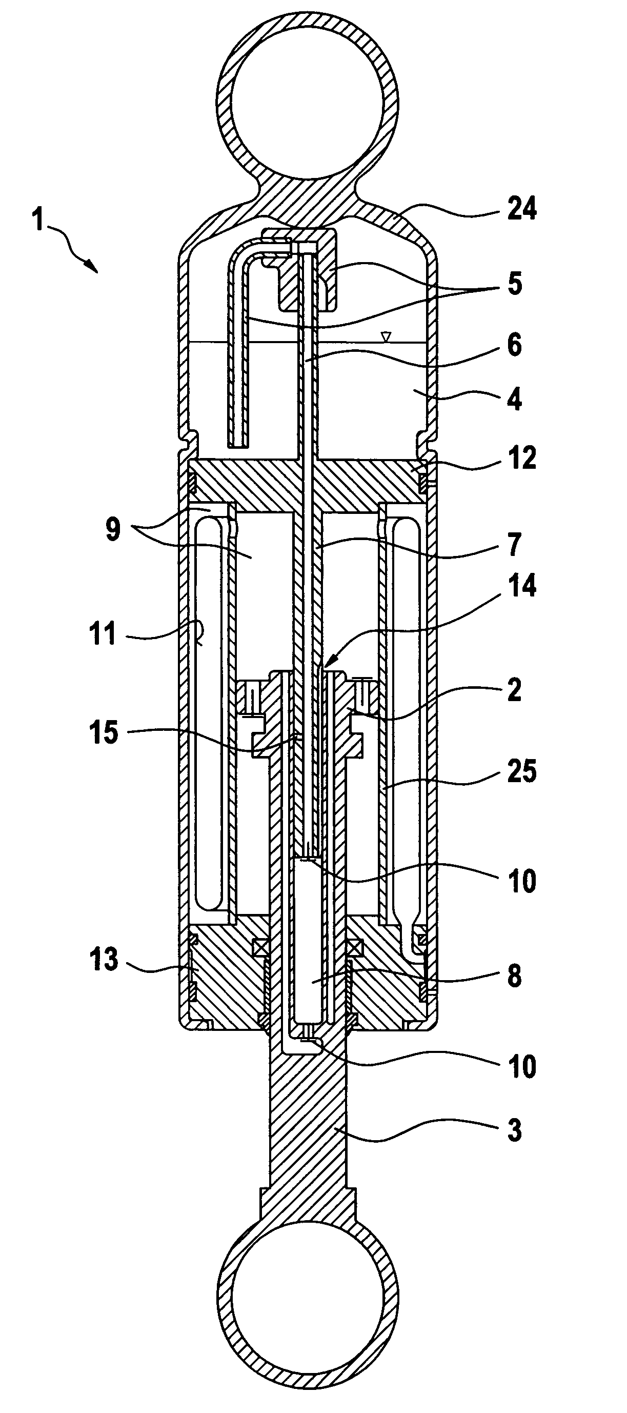
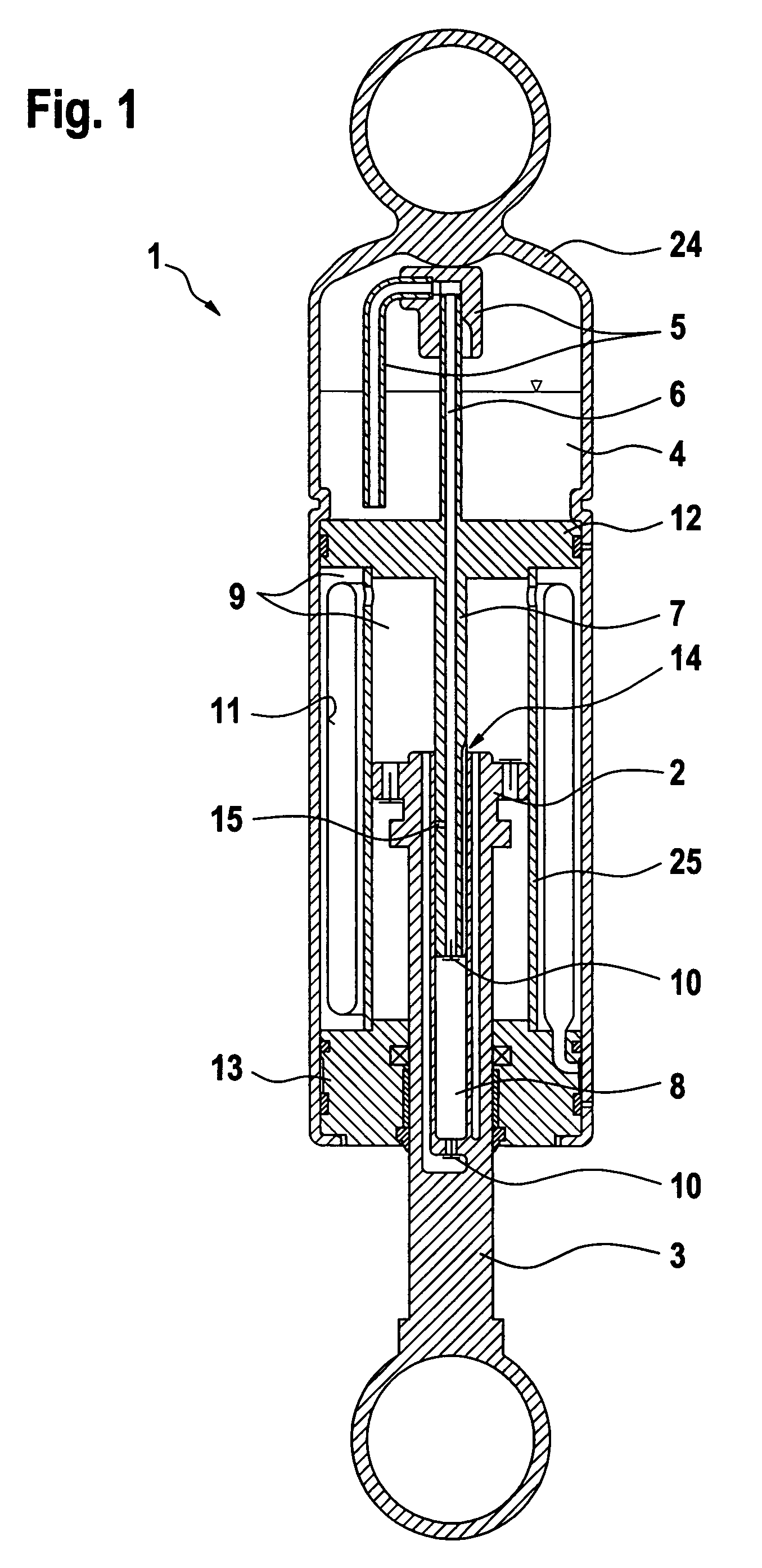
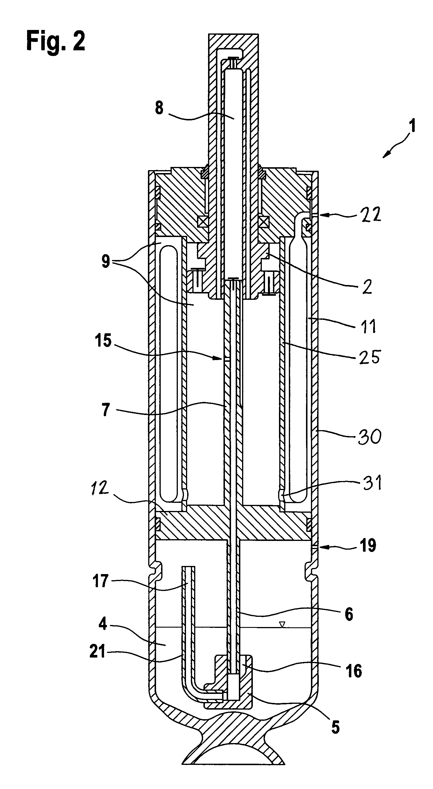
[0021]The self-pumping hydropneumatic suspension strut 1 shown in FIG. 1 includes on outer tube 30, a working cylinder 25, and a damping piston 2 mounted on the piston rod 3. The piston 2 divides the working cylinder 25 into two working spaces. In the axial direction, an intermediate wall 12 forms the boundary between a high-pressure chamber 9 and a low-pressure chamber 4. The high pressure chamber 9 includes an outer part which is pressurized by a compressed gas in a separating envelope 11, and an inner part formed by the working spaces. The inner and outer parts communicate via passages 31 in the working cylinder 25, so that they are at the same pressure. In the low-pressure chamber 4, the compressed gas and damping medium are both present, no separate measures being taken to keep them apart.

[0022]The suspension strut 1 in FIG. 1 is shown in the position it will occupy after installation in the vehicle; that is, the piston rod 3 carrying the damping piston 2 is directed downward. ...


PUM


Abstract

A suspension strut includes an outer tube having a first filling opening and a second filling opening, an intermediate wall received in the outer tube and separating a high pressure chamber from a low pressure chamber, a working cylinder located concentrically inside the outer tube in the high pressure chamber, and a gas filled separating envelope located between the working cylinder and the outer tube for pressurizing damping medium in the high pressure chamber. An axially displaceable piston divides the working cylinder into a first working space and a second working space, the first working space being connected to the high pressure chamber. A hollow piston rod passing through the second working space transports damping medium from the low pressure chamber to the first working space. A pump rod fixed to the intermediate wall and received in the hollow piston rod forms a pump cylinder, the pump rod having a suction tube extending into the low pressure chamber for transporting damping fluid from the low pressure chamber to the piston rod. A gas lock device fitted to suction tube prevents flow of gas from the low pressure chamber into the suction tube when the low pressure chamber is filled with damping medium and gas, and the suspension strut is vertically oriented with the low pressure chamber at the top.

Description

BACKGROUND OF THE INVENTION[0001]1. Field of the Invention[0002]The invention pertains to a self-pumping, hydropneumatic suspension strut with internal level control, especially for motor vehicles, having an outer tube having a first filling opening and a second filling opening, and an intermediate wall received in the outer tube, the intermediate wall separating a high pressure chamber from a low pressure chamber. The chambers each contain a damping medium, the first filling opening communicating with the low pressure chamber when the intermediate wall is not fully received in the outer tube and being closed by the intermediate wall when the intermediate wall is fully received in the outer tube. A working cylinder is located concentrically inside the outer tube in the high pressure chamber, and a gas filled separating envelope is located between the working cylinder and the outer tube for pressurizing the damping medium in the high pressure chamber. An axially displaceable piston d...

Claims


Application Information

Patent Timeline
Patent Type & Authority Patents(United States)
IPC IPC(8): B60G17/00B60G17/044F16F9/04
CPCB60G17/044F16F9/04
Inventor BECK, HUBERT
Owner ZF FRIEDRICHSHAFEN AG
Learn More