
Quadrature gain and phase imbalance correction in a receiver

a phase imbalance correction and gain technology, applied in the field of quadrature gain and phase imbalance correction in the receiver, can solve the problems of significant cost impact, q signal errors, q gain and phase errors, etc., and achieve the effect of low cos

Inactive Publication Date: 2006-04-25
MAXIM INTEGRATED PROD INC
View PDF10 Cites 44 Cited by
  • Summary
  • Abstract
  • Description
  • Claims
  • Application Information

AI Technical Summary

Benefits of technology

[0013]Therefore the present invention offers a low cost, reliable, on chip implementation that takes advantage of circuitry already present to detect and correct for all the different types of errors found in IQ quadrature receiver circuits.

Problems solved by technology

There are two major sources of I and Q signal errors in this type of receiver.
First, I and Q gain and phase errors result from the down conversion to base band or intermediate frequency IF cause by the mixing circuits.
Second, frequency dependent I and Q gain and phase error variations result within the pass band of the channel filters.
These types of errors are due to gain and phase mismatches between the quadrature receiver paths after down conversion (e.g. between the I and Q low pass filters and between the I and Q gain control blocks).
Such an approach has significant cost impact and may still not adequately address the problem.
The drawback of this technique is that all these feedback components (310–315) must be supplied in addition to the already required components found in I and Q receivers.
This adversely effects the cost and complexity of the device.
Further, even with all these extra circuit elements, adequate error compensation is not fully realized.
Other corrective devices such as a separate PLL and VCO are too costly to provide additionally.

Method used


Image

  • Quadrature gain and phase imbalance correction in a receiver
  • Quadrature gain and phase imbalance correction in a receiver
  • Quadrature gain and phase imbalance correction in a receiver

Examples


Embodiment Construction

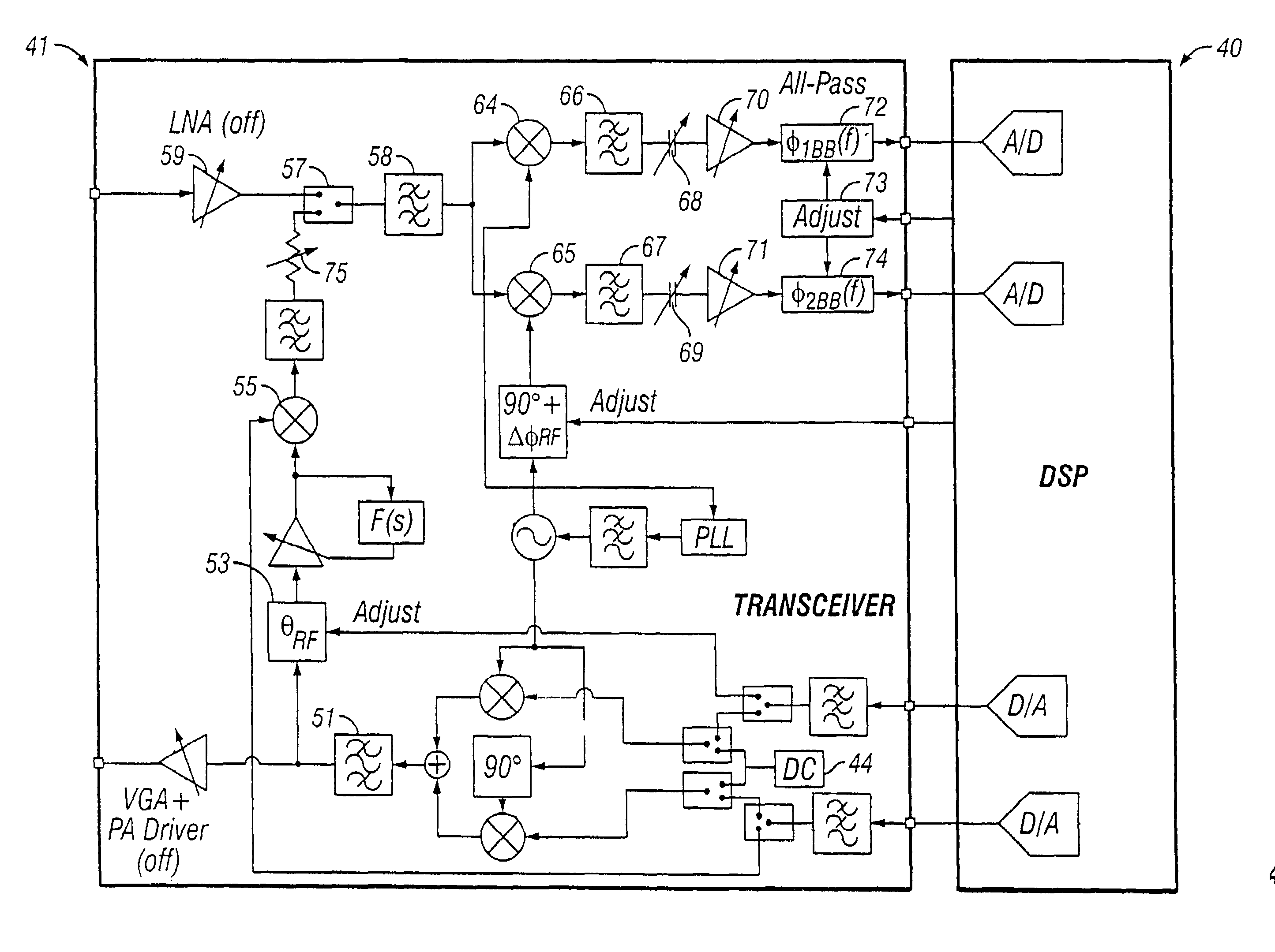
[0020]FIG. 2 shows one of the preferred embodiments of the present invention. FIG. 2 illustrates a communications device 10 suitable for receiving and correcting I and Q (In phase and Quadrature phase) signals. There are two essential parts to the device 10, the path of the received signals and the signal path of the signals used to mix with the received signals. In this embodiment the received signal path includes a low noise amplifier 11, two mixers 12 and 13, two coupling capacitors 14 and 15 and two filters 16 and 17. Finally the signal path contains gain amplifiers 18 and 19 before the received signal is input into A / D converters 20 and 21 for processing by the digital signal processor 22. The mixing signals are produced using local oscillators 23 and 24, a phase locked loop 25, a filter 26, a phase shifter 27 and a mixer 28.

[0021]In the received signal path, the LNA1 (11) is a standard low noise amplifier commonly used to amplify low power high frequency RF signals. The incomi...


PUM


Abstract

The present invention utilizes circuitry, already present in receivers, to calibrate and correct for gain and phase errors in a transceiver device. The present invention employs a digital signal processor along with multiple phase shifters and all pass networks to ensure proper levels of quadrature signals within the transceiver. An internally generated double sideband suppressed carrier signal is created to produce the calibration signals used by the digital signal processor.

Description

CROSS REFERENCE TO RELATED APPLICATIONS[0001]This application is a continuation in part of currently pending U.S. application Ser. No. 09 / 927,762 filed Aug. 10, 2001, which is herein incorporated by reference.STATEMENT REGARDING FEDERALLY SPONSORED RESEARCH[0002]NoneBACKGROUND OF THE INVENTION[0003]The invention relates to a method for correcting the gain and phase imbalance in quadrature paths of a receiver.[0004]In radio communication systems, different types of modulation schemes are employed to minimize the frequency spectrum necessary for communication and thereby maximize the call capacity of the radio communication system. The modulation schemes utilized usually involve converting the communication signal into discrete form, and the resultant modulated signal is typically of a reduced frequency spectrum.[0005]One method of transmitting a communication signal in discrete form is through the use of quadrature modulation. In quadrature modulation, the binary data stream of the e...

Claims


Application Information

Patent Timeline
IPC IPC(8): H04L5/12H04L27/00H04L27/38
CPCH04L27/3809H04L2027/0024H04L2027/0016
Inventor MOHINDRA, RISHI
Owner MAXIM INTEGRATED PROD INC
Learn More