
Method for testing pressing tablets

Active Publication Date: 2006-04-25
FETTE
View PDF3 Cites 0 Cited by
  • Summary
  • Abstract
  • Description
  • Claims
  • Application Information

AI Technical Summary

Benefits of technology

[0015]The inventive method allows to obtain a large series of benefits. Since it is necessary to fill only a single die or a very small number of dies with compression material the expense of compression material is very small. The loss of compression material is very small as well. Another substantial benefit of the invention is the one that the results of the test can be applied to every production-scale rotary press and that specific laboratory-type presses are unnecessary to make compression tests.
[0017]More benefits are found in the very short resetting times to other compression materials and ram types. The formation of dust during the compression tests is extremely low because of the small amount of compression material.

Problems solved by technology

At this stage, the product volumes which initially are available are very small and, in addition, are very expensive in both production and material so that production loses need to be kept low during compression.
Here, the drawback is that such laboratory-type presses exhibit a compression behavior different from than that of rotary tablet presses which are employed for production.
This is why the results of the compression tests cannot be readily transferred to a producing rotary press.

Method used


Image

  • Method for testing pressing tablets
  • Method for testing pressing tablets
  • Method for testing pressing tablets

Examples


Embodiment Construction

[0019]While this invention may be embodied in many different forms, there are described in detail herein a specific preferred embodiment of the invention. This description is an exemplification of the principles of the invention and is not intended to limit the invention to the particular embodiment illustrated

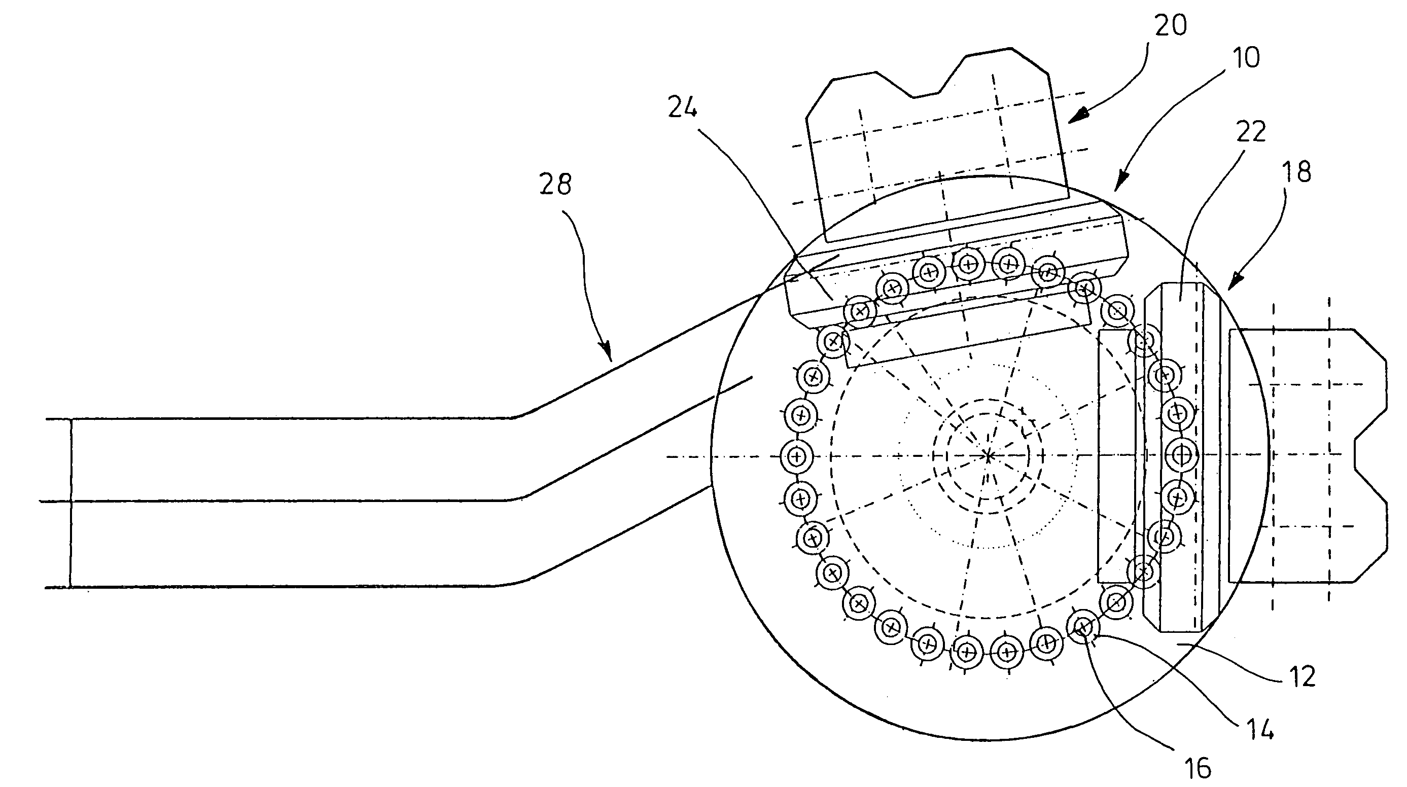
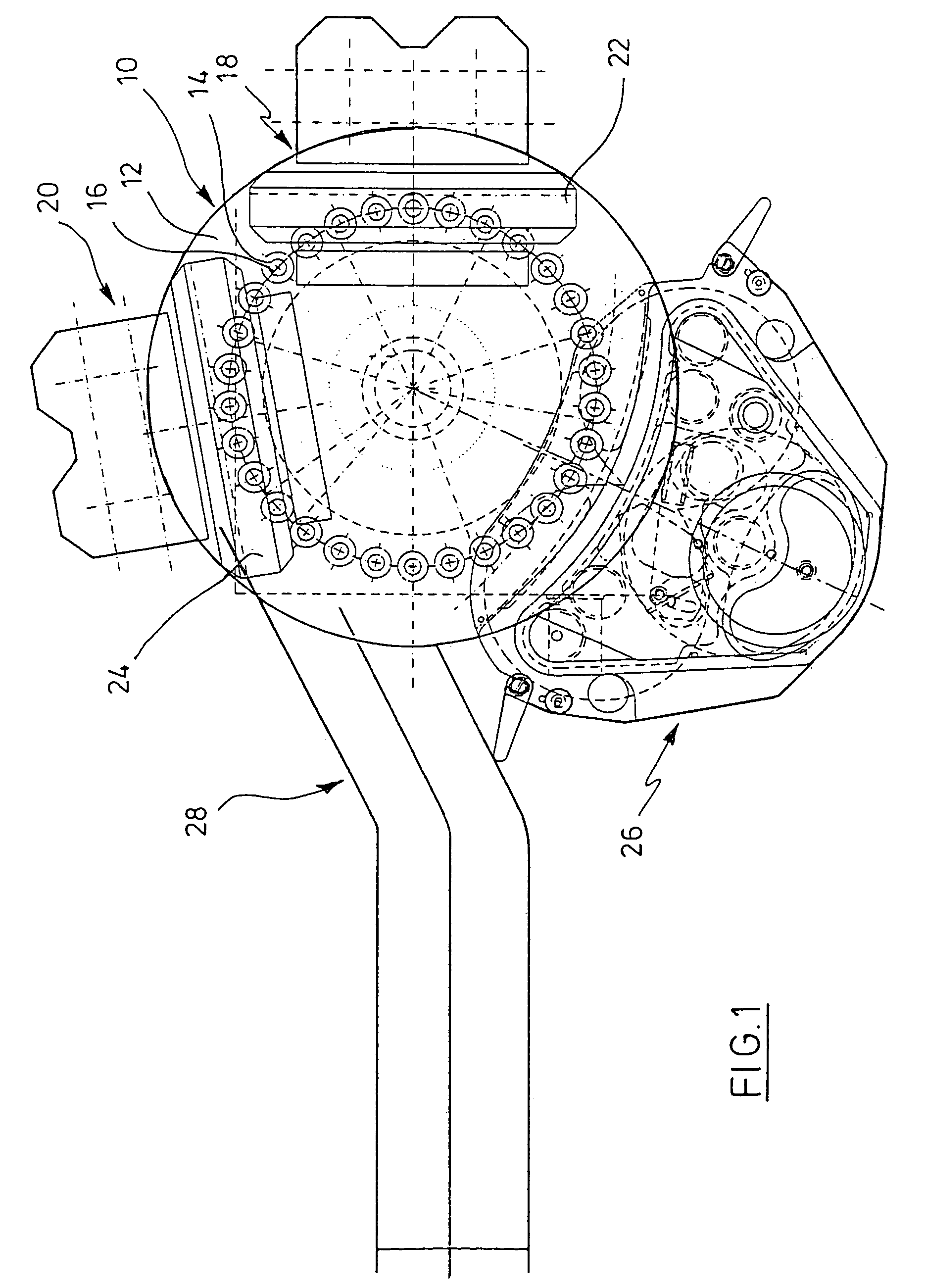
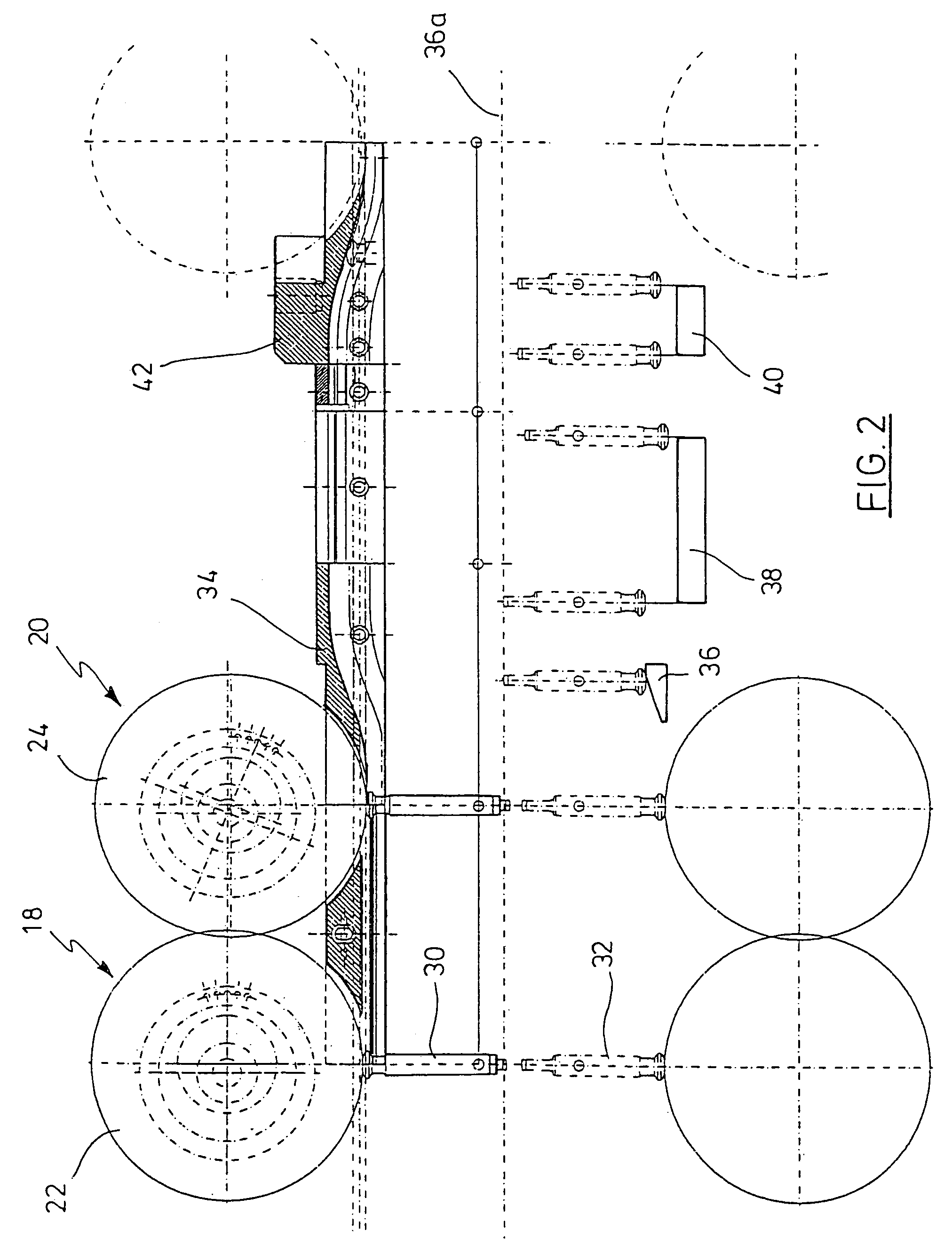
[0020]The invention will be described in more detail below with reference to the drawings.

[0021]FIG. 1 shows a plan view of a schematically illustrated tabletting machine of a conventional structure.

[0022]FIG. 2 schematically shows a developed view of the tabletting machine of FIG. 1 with no feed shoe.

[0023]FIG. 3 shows a view similar to that of FIG. 1, but with no feed shoe for the implementation of the inventive method.

[0024]FIG. 1 illustrates a rotor 10 of a rotary tabletting machine that has a die-plate 12 with a series of dies 14 which are disposed on a circle around the axis of the rotor 10, including die bores 16 to receive material to be compacted. Each die 14 or die b...


PUM


Abstract

A method for test pressing tablets by means of a rotary tabletting machine, a rotationally driven rotor which has a series of upper and lower rams, a die-plate with dies with which the rams interact, a control cam system for said rams, and a filling assembly to continuously fill said dies with said rotor rotating, further by means of at least one pressure station at which the material located in said dies is compressed into a tablet, and a measuring device having a plurality of measuring positions which measures at least the compression force applied by said rams and the number of revolutions of said rotor, comprising the process steps of, a pair of rams selected for a single compression procedure is automatically moved to a filling position, a die or limited number of dies is filled with material with said filling assembly removed at least in part and said rotor at stoppage, said rotor is set into rotation subsequently and is sped up such as to have the desired production speed in said pressure station, and said rotor is stopped in said filling position after a revolution and signals or signal sequences of the measuring positions are recorded while the rotor is rotating and are provided to a computer for display and evaluation.

Description

CROSS-REFERENCE TO RELATED APPLICATIONS[0001]Not applicable.STATEMENT REGARDING FEDERALLY SPONSORED RESEARCH[0002]Not applicable.BACKGROUND OF THE INVENTION[0003]It is common to make tablets in rotary tablet presses or rotary tabletting machines. Machines of this kind have a rotor with a die-plate which has a series of dies, further comprise upper and lower rams which interact with the dies, and at least one pressure station in which the rams are forced against the material filled into the die. This is done during the rotation of the rotor, which is driven by an appropriate driving mechanism. Prior to the compaction process, the dies require to be filled with the material to be compacted (powder). This is accomplished continuously, with the rotor rotating, in a so-called feed shoe or a filling assembly the arrangement of which is stationary.[0004]It is known that such a tablet press has associated therewith a measuring device which records substantial data during production and proc...

Claims


Application Information

Patent Timeline
IPC IPC(8): G01N3/08B30B11/00B30B11/08
CPCB30B11/08B30B11/005
Inventor HINZPETER, JUERGENSCHMIDT, INGOGATHMANN, ULRICHGAEDECKE, JOERG
Owner FETTE
Learn More