
Transmission apparatus and transmission method

Active Publication Date: 2006-04-18
SONY CORP
View PDF4 Cites 21 Cited by
  • Summary
  • Abstract
  • Description
  • Claims
  • Application Information

AI Technical Summary

Benefits of technology

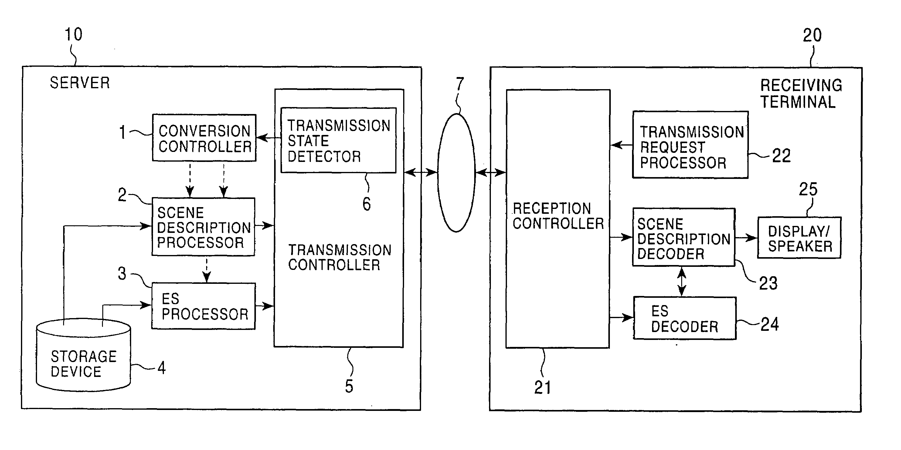
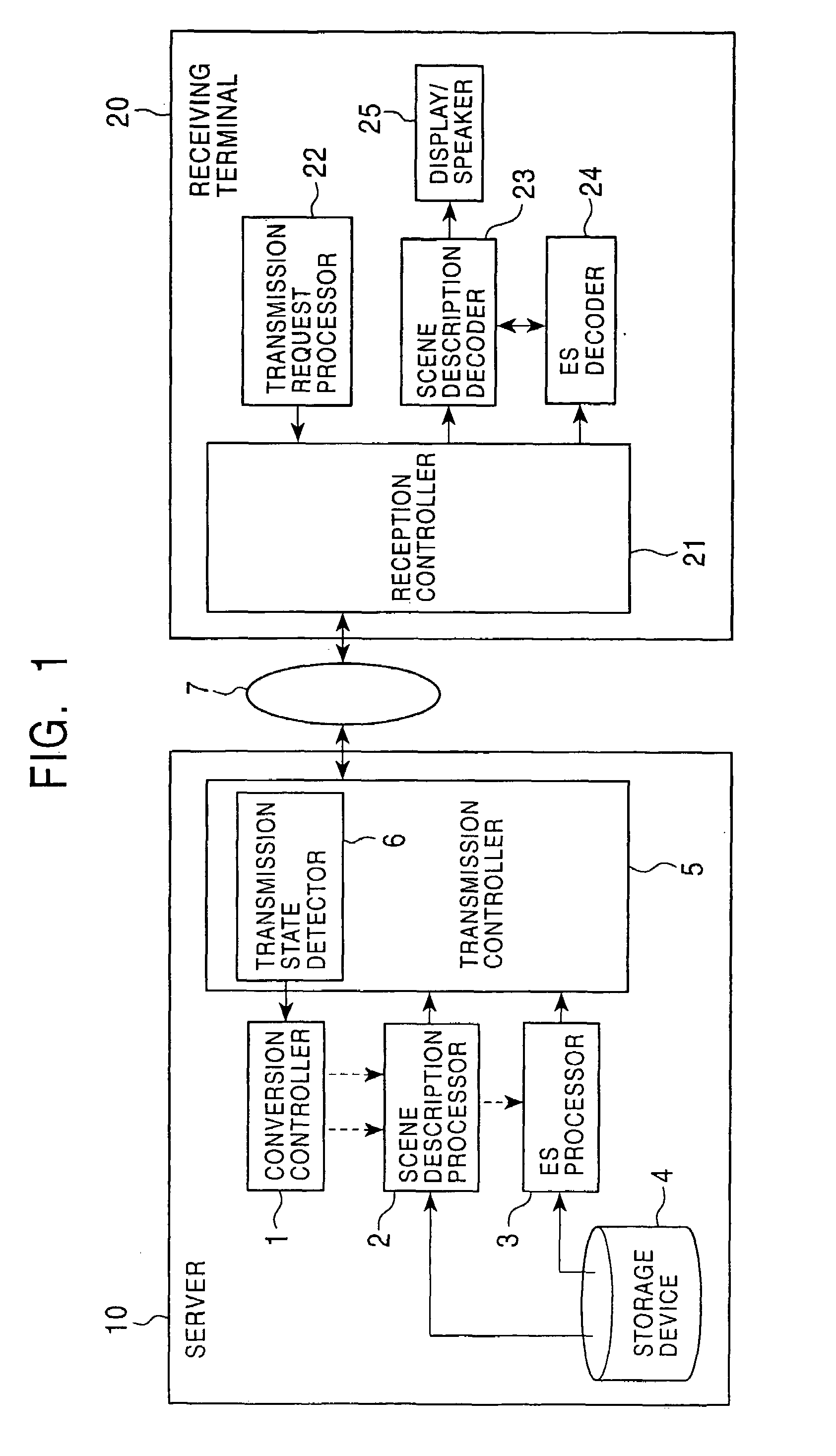
[0020]Accordingly, it is an object of the present invention to provide a transmission apparatus and a transmission method capable of obtaining the optimal ES and the optimal scene description with respect to the state of a transmission path and the processing capacity of a receiving terminal, detecting in advance the optimal scene description even if the processing capacity of a decoder of the receiving terminal dynamically changes, enabling the receiving terminal to display a scene with the optimal scene structure in response to a transmitted ES, and enabling a decoder / display terminal which reads an ES from a recording medium or a recording device and which decodes and displays the read ES to display a scene with the optimal scene structure in accordance with the processing capacity of the decoder / display terminal.
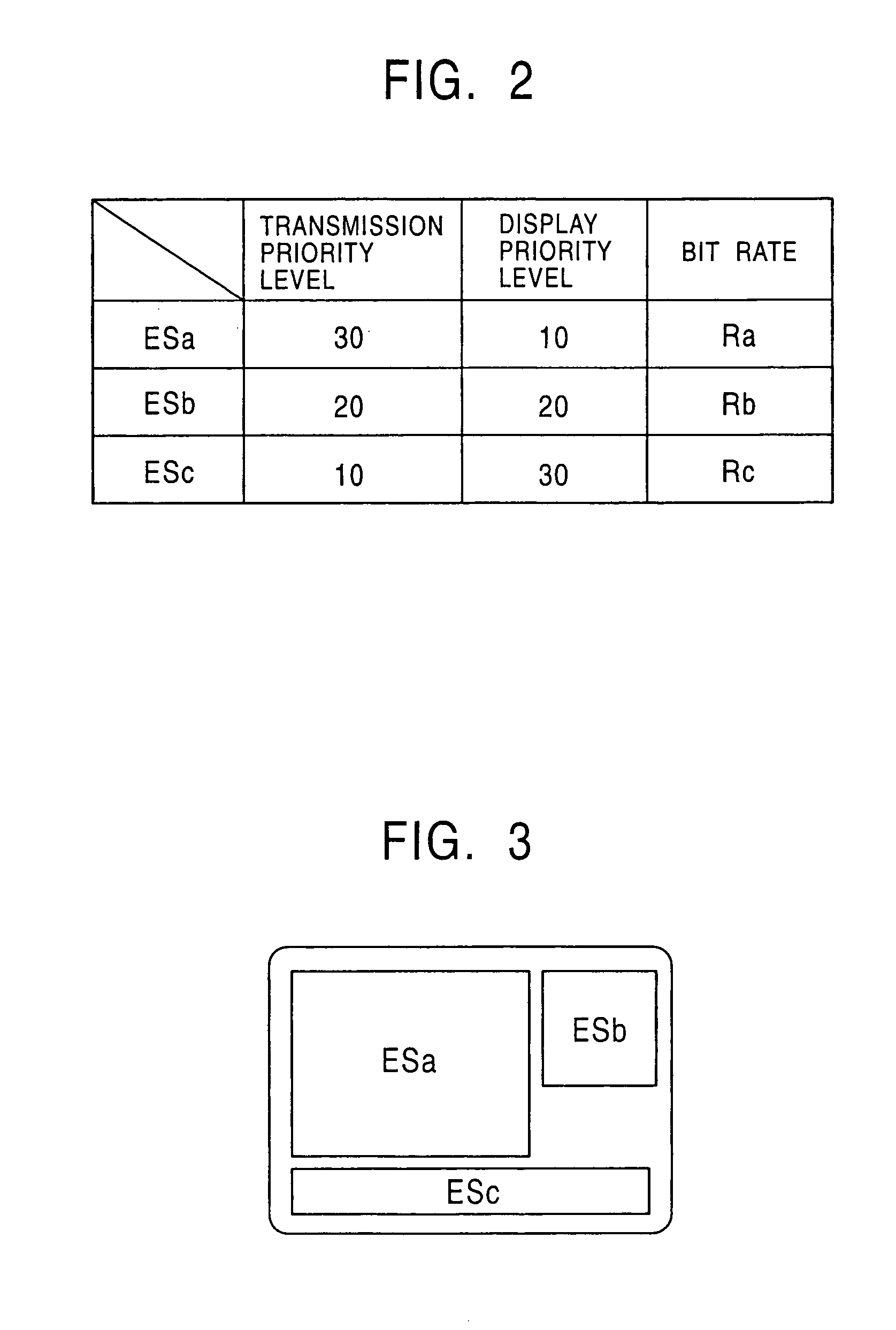
[0034]According to the present invention, when data formed of at least one signal is to be transmitted, and when the transmitted data is to be received, a transmission apparatus determines and transmits at least one signal to be transmitted based on a predetermined priority level in accordance with the state of a transmission path and / or a request from a receiving apparatus. Alternatively, the transmission apparatus in transmission adds priority level information regarding display with data to be transmitted and transmits the data. The receiving apparatus forms a scene in which a higher display region and / or a more preferential display position is assigned to the at least one signal in descending order of the priority levels. Alternatively, the receiving apparatus uses the transmitted at least one signal and forms a scene in accordance with the predetermined priority level. It is thus possible to obtain the optimal signal and the optimal scene structure in accordance with the state of the transmission path or the processing capacity of the receiving apparatus. Even when the processing capacity of a decoder of the receiving apparatus dynamically changes, it is possible to obtain in advance the optimal scene description. Also, the receiving apparatus can display a transmitted signal with the optimal scene structure. When decoding and displaying a signal read from a recording medium, a decoder / display apparatus can display a scene with the optimal scene structure in accordance with the processing capacity of the decoder / display apparatus.

Problems solved by technology

When a transmission bandwidth of a transmission path (transmission medium 107) for transmitting an ES changes or when the state of traffic congestion changes, data to be transmitted may be delayed or lost.
When scene description data is to be delivered over a transmission path such as the Internet in which the transmission capacity is variable and the transmission bandwidth varies in accordance with time or the path, or when an unspecified number of receiving terminals are connected to a server and when scene description data is to be delivered to the receiving terminals which have different specifications and various processing capacities, it is difficult for the conventional data delivery system to detect in advance the optimal scene structure for the transmission path and the receiving terminal.
In such a case, the conventional data delivery system cannot detect in advance the optimal scene description.

Method used


Image

  • Transmission apparatus and transmission method
  • Transmission apparatus and transmission method
  • Transmission apparatus and transmission method

Examples


first embodiment

[0060]The configuration and the operation described so far are the same as the example shown in FIG. 15. However, in the data delivery system of the first embodiment, the conversion controller 1 of the server 10 controls not only the ES processor 3 but also the scene description processor 2 in accordance with the state of the transmission path, which is detected by the transmission state detector 6. When the receiving terminal 20 requests a scene description that complies with the coding and display performance thereof, the conversion controller 1 of the server 10 controls the ES processor 2 and the scene description processor 3 in accordance with a signal which indicates the capacity of the receiving terminal 20 and which is transmitted from the transmission request processor 22 of the receiving terminal 20. The conversion controller 1, the scene description processor 2, and the ES processor 3 can be integrated.

[0061]A selection method for selecting, by the ES processor 3 of the fi...

second embodiment

[0094]FIG. 13 shows a data delivery system according to the present invention. Referring to FIG. 13, the same reference numerals are given to components corresponding to those in FIG. 1, and repeated descriptions of the common portions are omitted.

[0095]A server 30 of the data delivery system of the second embodiment does not include a scene description processor, and hence the server 30 does not transmit a scene description to a receiving terminal 40. The server 30 of the data delivery system transmits an ES and its display priority level information. The server 30 of the data delivery system of the second embodiment is basically the same as the server 10 of the data delivery system shown in FIG. 1 except for the point that the server 30 does not transmit a scene description and that the server 30 transmits display priority level information. The receiving terminal 40 of the data delivery system of the second embodiment includes a scene forming unit 43 instead of receiving and deco...

fourth embodiment

[0106] scene description data is not recorded in the recording medium 55 or in the storage device 58. Thus, the transmission capacity required for the scene description data can be saved.

[0107]According to the fourth embodiment, since the data decoder / display terminal 50 forms a scene, it is possible to form a scene in accordance with the processing capacity of the data decoder / display terminal 50. Specifically, as in the second embodiment, the scene forming unit 43 sequentially obtains ES's in descending order of the display priority levels, within a limit of the processing capacity of the data decoder / display terminal 50. If an ES exceeds the processing capacity of the data decoder / display terminal 50, the ES is not incorporated into a scene. It is thus possible to form a scene in accordance with the processing capacity of the data decoder / display terminal 50. In particular, if the ES decoder 24 and the scene forming unit 43 of the data decoder / display terminal 50 are formed by so...


PUM


Abstract

A transmission system is a data delivery system which includes a server for transmitting ES data and a receiving terminal for receiving the transmitted data. The server includes a conversion controller for determining elementary streams (ES's) and a scene description to be transmitted based on transmission priority levels and display priority levels, in accordance with the state of a transmission path and / or a request from the receiving terminal. The server also includes an ES processor and a scene description processor.

Description

BACKGROUND OF THE INVENTION[0001]1. Field of the Invention[0002]The present invention relates to transmission apparatuses and transmission methods which are suitable for delivering, via a network or a recording medium, scene description data for forming a scene using multimedia data including still image signals, moving image signals, audio signals, text data, and graphic data, the scene description data being in turn received, decoded, read, and displayed by a receiving terminal.[0003]2. Description of the Related Art[0004]FIG. 15 shows the configuration of a conventional data delivery system for transmitting moving image signals and audio signals through a transmission medium, the signals being in turn received, decoded, and displayed by a receiving terminal. In the following description, a moving image signal or an audio signal which is coded in conformity with the ISO / IEC 13818 standard (so-called MPEG 2) or the like is referred to as an elementary stream (ES).[0005]Referring to...

Claims


Application Information

Patent Timeline
IPC IPC(8): H04L12/28H04L12/56H04L29/06H04L29/08H04N7/24H04N19/00H04N19/102H04N19/134H04N19/157H04N19/162H04N19/164H04N19/167H04N19/27H04N19/37H04N21/234H04N21/2343H04N21/24H04N21/262H04N21/2662H04N21/431H04N21/44H04N21/6373H04N21/647
CPCH04L29/06H04N21/23412H04N21/234318H04N21/234327H04N21/2402H04N21/26216H04N21/2662H04N21/4312H04N21/4314H04N21/44012H04N21/6373H04N21/64769H04L65/607H04L65/80H04L67/08H04L67/02H04L69/329H04L29/06027H04L65/70H04L9/40H04L65/1101
Inventor NEGISHI, SHINJIKOYANAGI, HIDEKIYAGASAKI, YOICHI
Owner SONY CORP
Learn More