
Vehicle surroundings monitoring apparatus and traveling control system incorporating the apparatus

Inactive Publication Date: 2006-04-18
FUJI JUKOGYO KK
View PDF12 Cites 138 Cited by
  • Summary
  • Abstract
  • Description
  • Claims
  • Application Information

AI Technical Summary

Benefits of technology

[0008]It is an object of the present invention to provide a vehicle surroundings monitoring apparatus capable of monitoring exterior circumstances of a vehicle with high precision by efficiently utilizing both exterior information based on picture images and exterior information obtained from a radar and to provided a traveling control system incorporating such an apparatus.

Problems solved by technology

In these vehicle surroundings monitoring apparatuses sometimes the ability of recognizing the preceding vehicle and the like is exacerbated due to adverse conditions such as rain, snow, fog, backlight, knighting driving and the like.
However, the technology disclosed in Toku-Kai-Hei 6-230115 has a disadvantage that since the respective reliabilities of stereoscopic camera and millimeter wave radar are judged simply on the basis of the external circumstances, a proper intervehicle distance is rejected and wrong data are adopted in some cases.
Further, in the prior art, since only one of the two ways is adopted and the other is discarded as invalid, distance data of the vehicle surroundings monitoring apparatus are not efficiently used.

Method used


Image

  • Vehicle surroundings monitoring apparatus and traveling control system incorporating the apparatus
  • Vehicle surroundings monitoring apparatus and traveling control system incorporating the apparatus
  • Vehicle surroundings monitoring apparatus and traveling control system incorporating the apparatus

Examples


Embodiment Construction

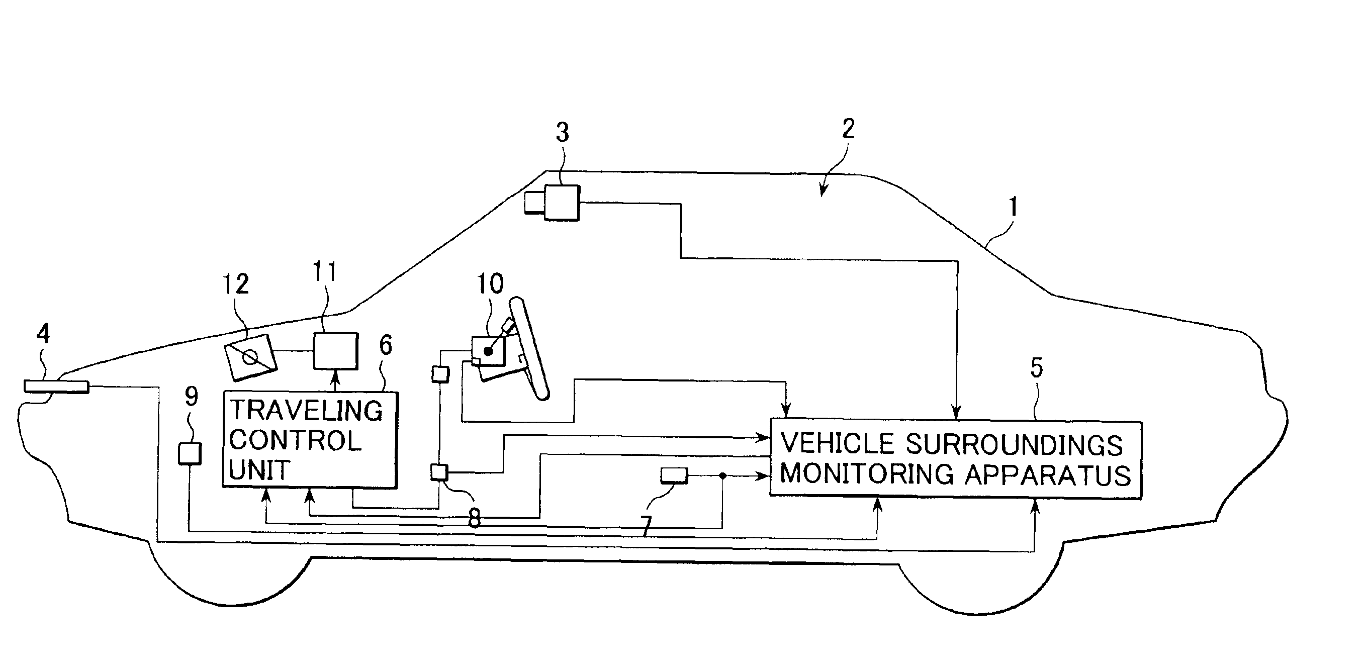
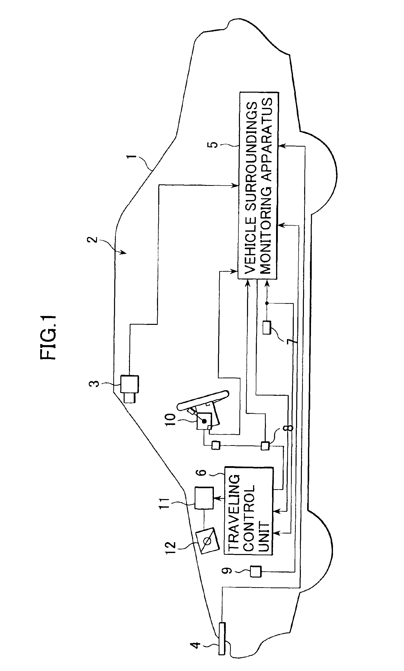
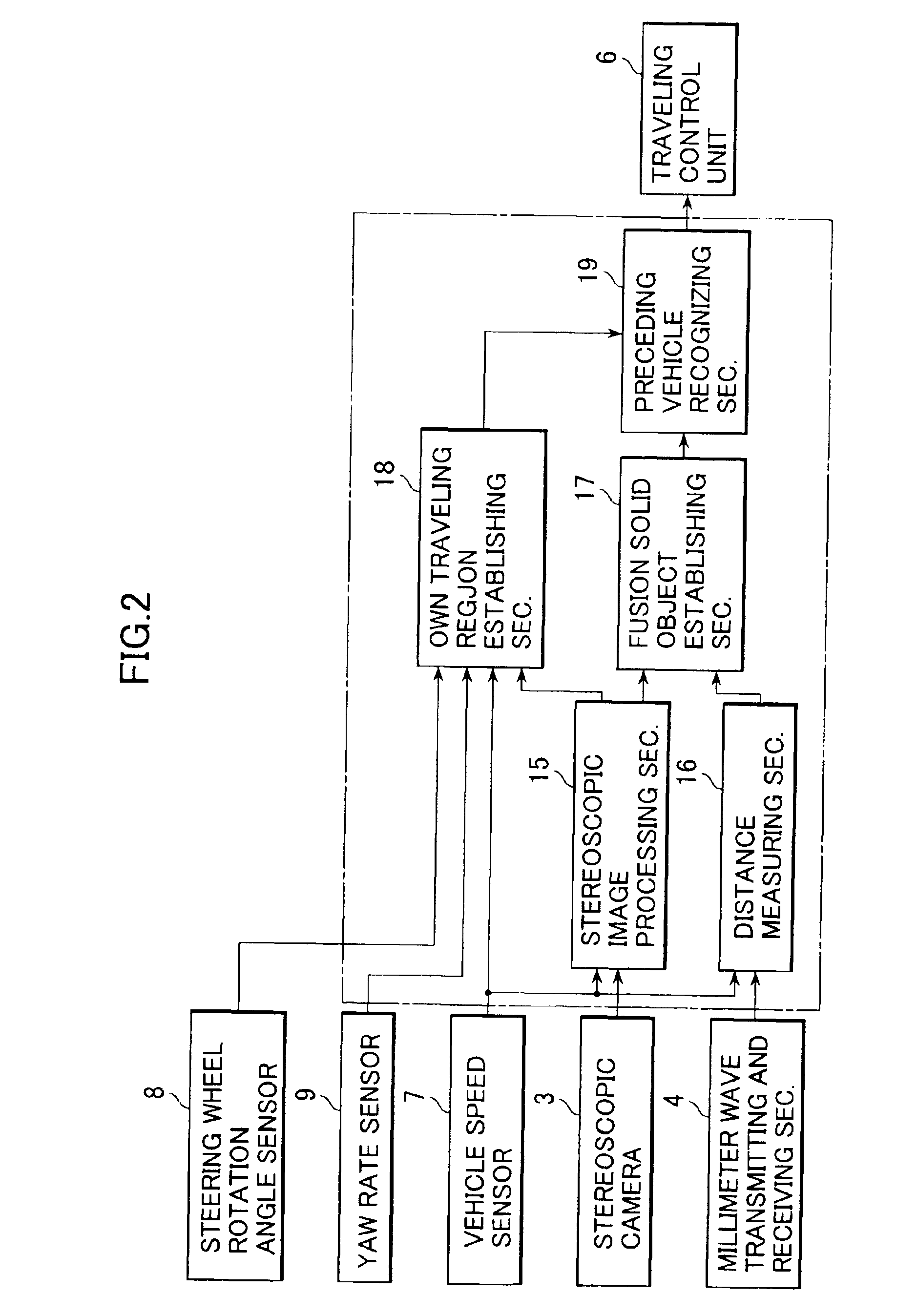
[0014]Referring now to FIG. 1, reference numeral 1 denotes a vehicle (own vehicle) on which an intervehicle distance automatically adjusting system (Adaptive Cruise Control: ACC) 2 is mounted. The ACC system 2 is constituted by a stereoscopic camera (imaging means) 3, a millimeter wave transmitting and receiving section (radar means) 4, a vehicle surroundings monitoring apparatus 5 and a traveling control unit 6. When the ACC system is set to a constant speed control mode, the vehicle travels at a speed established by a vehicle driver and when the system is set to a follow-up traveling control mode, the vehicle travels at a speed targeted to the speed of a preceding vehicle with a constant intervehicle distance to the preceding vehicle maintained.

[0015]The stereoscopic camera 3 is composed of a pair (left and right) of CCD cameras using a solid-state image component such as Charge Coupled Device and the left and right cameras are transversely mounted on a front ceiling of a passenge...


PUM


Abstract

A vehicle surroundings monitoring apparatus comprises image solid object detecting means for detecting image solid objects based on image information outputted from a CCD camera, millimeter wave solid object detecting means for detecting millimeter wave solid objects based on signals outputted from a millimeter wave radar, fusion solid object establishing means for establishing fusion solid objects composed of single image solid objects, single millimeter wave solid objects and a combination of the image solid objects and the millimeter wave solid objects by fusing the image solid objects and the millimeter wave solid objects, first reliability judging means for judging a degree of reliability of the fusion solid objects based on a detecting situation of the respective fusion solid objects by the image solid object detecting means, second reliability judging means for judging a degree of reliability of the fusion solid objects based on a detecting situation of the respective fusion solid objects by the millimeter wave solid object detecting means and preceding vehicle selecting means for selecting a preceding vehicle from the fusion solid objects when it is judged that the fusion solid objects have a specified level of reliability according to either of the first reliability judging means and the second reliability judging means.

Description

BACKGROUND OF THE INVENTION[0001]1. Field of the Invention[0002]The present invention relates to a vehicle surroundings monitoring apparatus employing together a monitoring technique on the base of images and a monitoring technique using radar data and a traveling control system incorporating the apparatus.[0003]2. Discussion of Related Arts[0004]In recent years, such vehicle surroundings monitoring apparatuses as detecting traveling circumstances in front of an own vehicle by means of processing images taken by a camera mounted on a vehicle and the like and detecting information about a preceding vehicle traveling ahead of the own vehicle from the traveling circumstances, have been proposed. Further, various traveling control systems in which a follow-up control to the preceding vehicle or an intervehicle distance control between the own vehicle and the preceding vehicle are performed using such vehicle surroundings monitoring apparatuses, have been put into practical use.[0005]In ...

Claims


Application Information

Patent Timeline
IPC IPC(8): G08G1/16G01C3/06B60K31/00B60Q1/00B60R1/00B60R21/00G01S13/86G01S13/93H04N7/18
CPCB60K31/0008
Inventor SEKIGUCHI, HIROYUKI
Owner FUJI JUKOGYO KK
Learn More