Eureka AIR delivers breakthrough ideas for toughest innovation challenges, trusted by R&D personnel around the world.

Multi stage selective catalytic cracking process and a system for producing high yield of middle distillate products from heavy hydrocarbon feedstocks

a selective catalytic cracking and high yield technology, applied in catalytic cracking, hydrocarbon oil treatment, lighting and heating apparatus, etc., can solve the problems of high amount of recycle oil fed to the bottom of the riser with fresh feed, unconverted bottom yield increases to a significant extent, and reduces the throughput of the riser reactor. , the effect of improving the cetane quality of the middle distillate produ

Inactive Publication Date: 2006-04-18
INDIAN OIL CORPORATION
View PDF16 Cites 92 Cited by
  • Summary
  • Abstract
  • Description
  • Claims
  • Application Information

AI Technical Summary

Benefits of technology

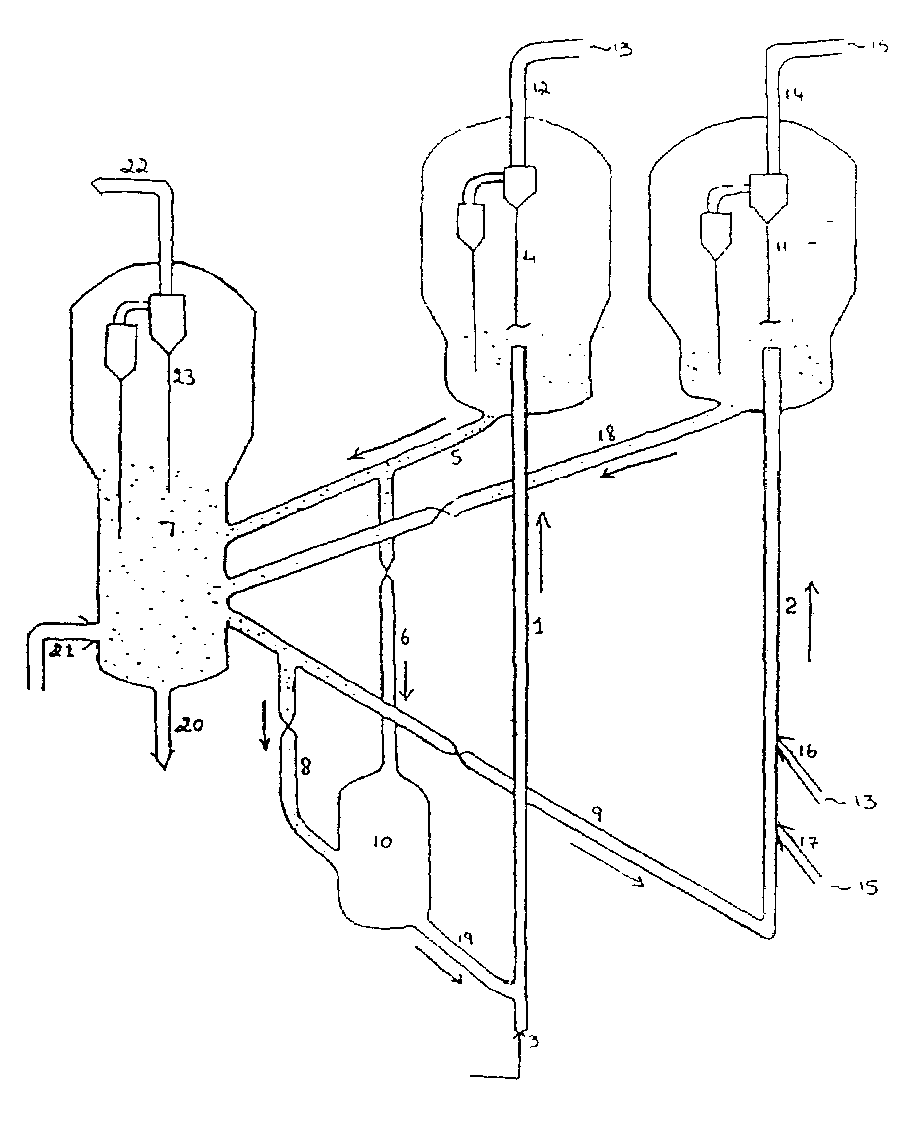
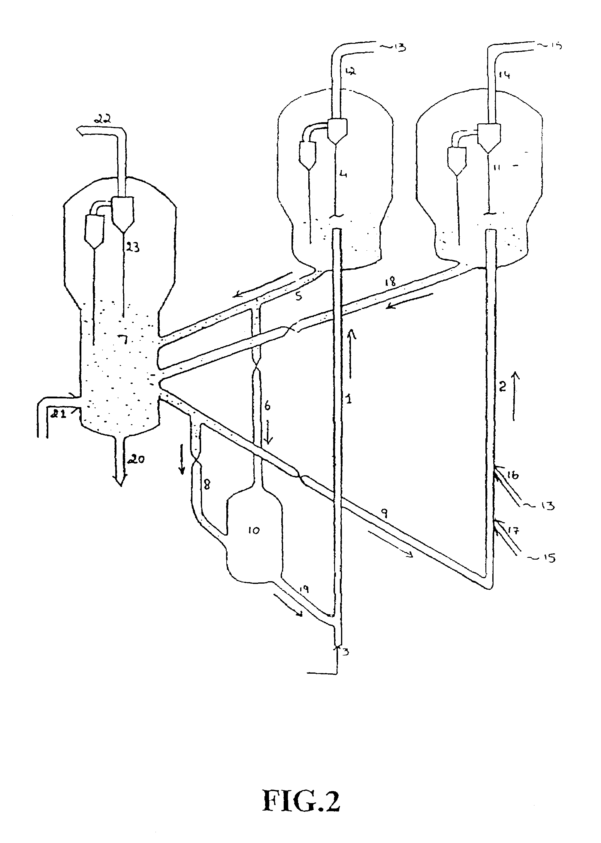
[0012]Accordingly, one object of the present invention aims to propose a novel catalytic cracking process for producing middle distillate products in very high yield (about 50–65 wt %).
[0013]Another object is to provide a multiple riser system that enables the production of middle distillate products, including heavy naphtha and light cycle oil in high yield.
[0014]Yet another object of the invention is to provide a multiple riser system to produce higher yield of heavy naphtha and light Cycle Oil as compared to the prior art processes employing catalytic cracking of petroleum feedstock without any use of external supply of hydrogen.

Problems solved by technology

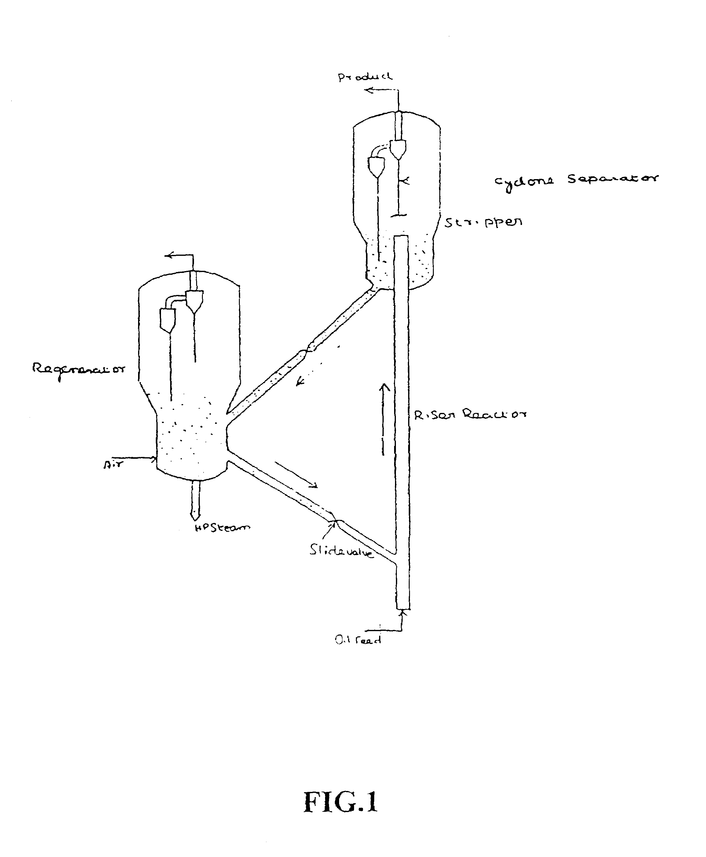
However, while running at low severity operations for maximizing diesel yield, the unconverted bottom yield also increases to a significant extent and sometimes may even exceed 20 wt % of fresh feed, as against 5–6 wt % for the usual gasoline mode operation.
The other drawback of low severity operation is in the high amount of recycle oil being fed to the bottom of the riser with fresh feed for further cracking.
Firstly, this reduces the throughput of riser reactor and secondly, with a single riser and product fractionator, the recycle is nonselective.
Further, persons involved in fluid catalytic cracking would be aware that middle distillate, being an intermediate product in the complex catalytic cracking reactions, is very difficult to maximize because, when the severity is increased, it is over cracked to lighter hydrocarbons.

Method used


Image

  • Multi stage selective catalytic cracking process and a system for producing high yield of middle distillate products from heavy hydrocarbon feedstocks
  • Multi stage selective catalytic cracking process and a system for producing high yield of middle distillate products from heavy hydrocarbon feedstocks
  • Multi stage selective catalytic cracking process and a system for producing high yield of middle distillate products from heavy hydrocarbon feedstocks

Examples


example-1 (

PRIOR ART)

Yield of Middle Distillate at Different Conversions in Conventional FCC Operation

[0076]This example illustrates the change in yield of the middle distillate product (TCO) at different conversion levels under conventional FCC conditions. −216° C. conversion is defined as the total quantity of products boiling below 216° C. including Coke. Similarly −370° C. conversion is defined as the total quantity of products boiling below 370° C. including Coke. The experiments were conducted in standard fixed bed Micro Activity Test (MAT) reactor described as per ASTM D-3907 with minor modifications indicated subsequently as modified MAT. The catalyst to be used is first steamed at 788° C. for 3 hours in presence of 100% steam. The physico-chemical properties of the feed used in the modified MAT reactor are given in the following Table-4 & 5.

[0077]

TABLE 4Density @ 15° C., gm / cc0.8953CCR, wt %0.32Sulfur, wt %1.12Basic Nitrogen, PPM366Paraffins, wt %44.4Naphthenes, wt %18.1Aromatics, wt ...

example-2

Effect of Reaction Temperature on Middle Distillate Yields at Same Conversion

[0083]This example illustrates the effect of reaction temperature on the yield of middle distillate at a given −216° C. conversion. The experiments were conducted in the modified MAT reactor with the same feed as mentioned in Example-1, at two different temperatures, viz., 425° C. and 495° C. Catalyst employed here is catalyst C which is commercially available FCC catalyst of following properties as shown in the Table-8.

[0084]

TABLE 8Catalyst-CSurface Area, m2 / gmFresh172Steamed119Pore volume, cc / gm0.32Crystallinity, %Fresh13.80Steamed10.20UCS ° AFresh24.55Steamed24.31Chemical Analysis, wt %RE2O30.69Al2O336.40Na2O0.11Particle size, micron / wt %−20 / −40 / −60 / −80 / −105 / −1203 / 16 / 32 / 56 / 77 / 86APS, micron76

[0085]

TABLE 9Temperature, ° C. II425495−216° C. conversion, wt %30503050W / F, Min.1.12.70.100.5Yield Pattern, wt %Dry gas0.200.420.380.56LPG4.109.15.0710.72Gasoline14.9423.5216.0024.58Heavy naphtha9.5014.277.1111.20LCO...

example-3

First Stage Riser Cracking Conditions

[0087]This example illustrates the significance of first stage riser cracking conditions, e.g., temperature, catalyst / oil ratio and conversion, on the yield of middle distillate and other products while employing commercially available FCC catalysts A and C, properties of which are described in Example-1 & 2 respectively. The tests were conducted in modified fixed bed MAT unit with same feed as described in Example-1. Yield data were generated at different conversion level for the catalysts as indicated above and the yields of different products were obtained. TCO / Rest ratios at different conversion levels are plotted in FIG.-3, from which it is observed that for both the catalysts, the TCO / Rest ratio increases as the −370° C. conversion is reduced. Therefore, it is important to note that the per pass −370° C. conversion in the first stage riser should be kept below about 45% and preferably below 40%.

[0088]From FIG.-3, it is also observed that th...


PUM


Abstract

According to this invention, there is provided a process and apparatus for catalytic cracking of various petroleum based heavy feed stocks in the presence of solid zeolite catalyst and high pore size acidic components for selective bottom cracking and mixtures thereof, in multiple riser type continuously circulating fluidized bed reactors operated at different severities to produce high yield of middle distillates, in the range of 50–65 wt % of fresh feed.

Description

FIELD OF THE INVENTION[0001]This invention relates to a process and a system for the improved production of middle distillate products comprising hydrocarbons having carbon atoms in the range of C8 to C24 in high yield, from heavier petroleum fractions through multistage catalytic cracking of varying severity levels with solid acidic catalyst without using external hydrogen.BACKGROUND OF THE INVENTION[0002]Conventionally, middle distillate range products, e.g. heavy naphtha, kerosene, jet fuel, diesel oil and light cycle oil (LCO), are produced in petroleum refineries by atmospheric / vacuum distillation of petroleum crude and also by the secondary processing of vacuum gas oil and residues or mixtures thereof. Most commonly practiced commercial secondary processes are Fluid Catalytic Cracking (FCC) and Hydrocracking. Hydrocracking employs porous acidic catalysts similar to those used in catalytic cracking but associated with hydrogenation components such as metals of Groups VI and VII...

Claims


Application Information

Patent Timeline
IPC IPC(8): C10G51/02B01J8/08C10G11/18C10G51/04
CPCC10G51/026C10G11/18
Inventor BHATTACHARYYA, DEBASISDAS, ASIT KUMARKARTHIKEYANI, ARUMUGAM VELAYUTHAMDAS, SATYEN KUMARKASLIWAL, PANKAJSANTRA, MANORANJANSAROYA, LATOOR LALDIXIT, JAGDEV KUMARMISHRA, GANGA SANKERSINGH, JAI PRAKASHMAKHIJA, SATISHGHOSH, SOBHAN
Owner INDIAN OIL CORPORATION
Why Eureka
Eureka Blog
Learn More