
Process and device for adjusting a movable motor vehicle part

a technology for moving motor vehicles and parts, applied in the direction of alarms, color televisions, television systems, etc., can solve the problems of complex and expensive pinch protection, described anti-pinching systems,

Active Publication Date: 2006-04-11
WEBASTO VEHICLE SYST INT
View PDF27 Cites 18 Cited by
  • Summary
  • Abstract
  • Description
  • Claims
  • Application Information

AI Technical Summary

Benefits of technology

[0021]If the perturbing object, such as, for example, an individual, is detected within the monitoring area, it can be a good idea to deliver a warning signal in order to warn him accordingly against possible pinching. This warning signal is, for example, an optical or acoustic signal or both. In this way, pinch protection can be accomplished even more efficiently. However, the warning signal can also be useful for the operator of the adjustment mechanism so that he is notified, for example, that the drive is being stopped or reversed and why. However, it is also conceivable to divide the monitoring area into an outer and an inner area, and when an object enters the outer area a warning signal can be delivered and only when the object enters the inner area is the drive stopped or reversed. The outer boundary of the monitoring area should not have a distance from the motor vehicle which is too great, since otherwise objects could also be detected which do not constitute perturbing objects in the sense of the invention, i.e., which need not be protected against pinching since they do not come too near the movable motor vehicle part.
[0023]For reasons of cost, it is advantageous to use possibly already present sensors and / or cameras which are used, for example, for support during parking or in general to improve the visibility for the driver. For this purpose, suitable signal processing or signal evaluation can be incorporated into the existing electrical control of the motor vehicle.

Problems solved by technology

Since these sensors must be provided over the entire width of the roof opening to accomplish effective pinching protection, this pinch protection is very complex and expensive.
The above described anti-pinching systems have the disadvantage that they only react when clamping forces occur.

Method used


Image

  • Process and device for adjusting a movable motor vehicle part
  • Process and device for adjusting a movable motor vehicle part
  • Process and device for adjusting a movable motor vehicle part

Examples


Embodiment Construction

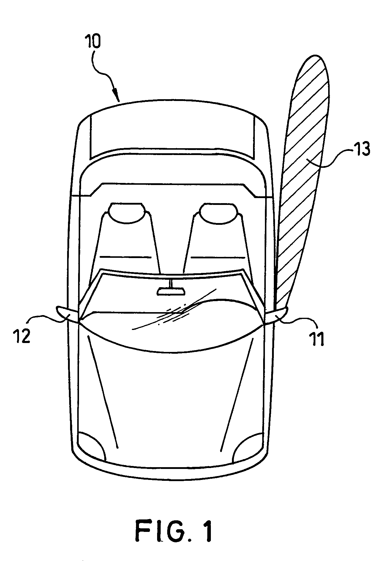
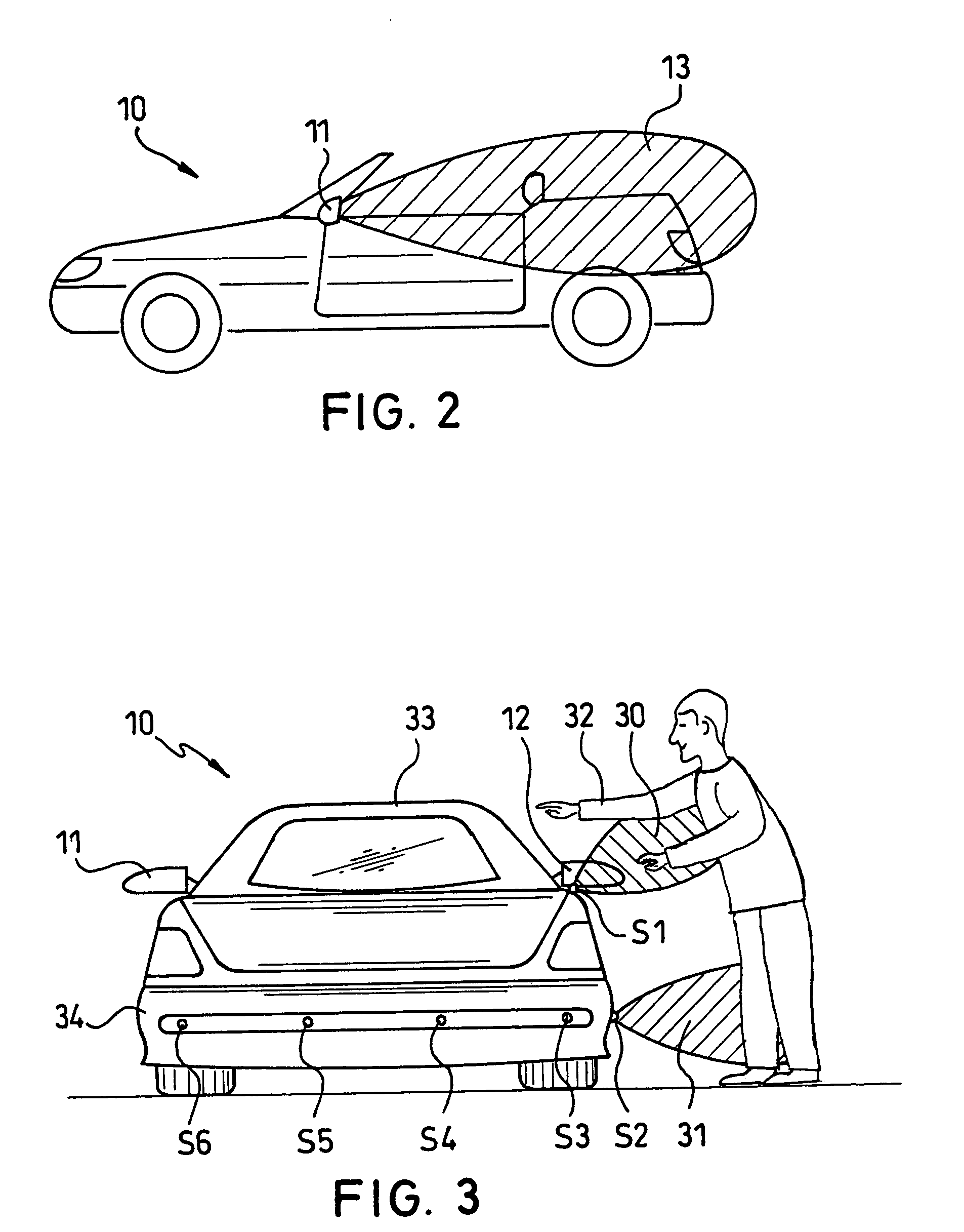
[0029]FIG. 1 shows a motor vehicle 10 in the form of a convertible with an opened roof A sensor (not shown), which covers a limited monitoring area 13, is attached to one of the two outside mirrors 11,12. Of course, the corresponding monitoring area of a corresponding sensor can also be set up on the other outside mirror. A side view of monitoring area 13 is shown in FIG. 2. Here, it is apparent that the monitoring area is set up above the roadway. This can be sufficient, since the monitoring area covers most of the side pinch danger area. For this purpose, only one sensor, for example, an ultrasonic sensor, is required, for example.

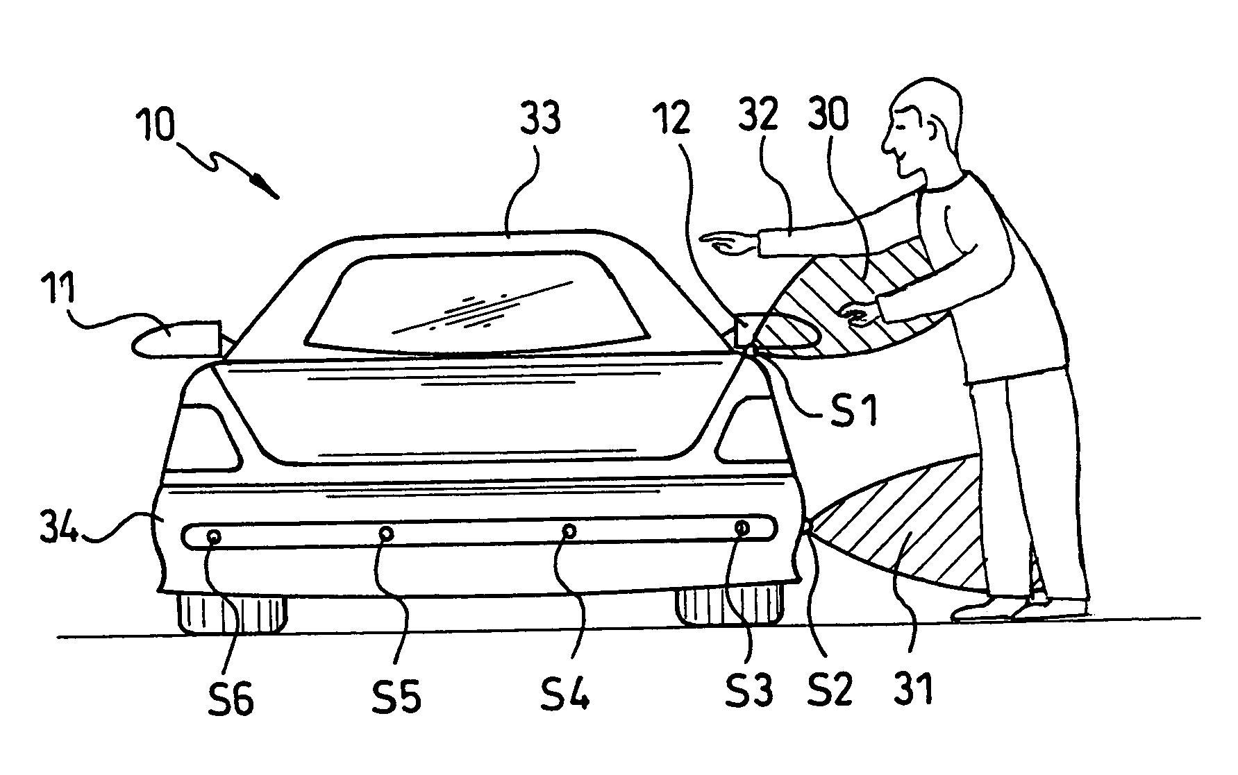
[0030]Another embodiment of the invention is shown in FIG. 3. A motor vehicle 10 in a rear view is shown there. Sensors S1 to S6 are mounted at different locations on the vehicle. A sensor S1 is located on the outer side mirror and covers a partial monitoring area 30. Another sensor S2 is located laterally underneath on the bumper and covers the partial ...


PUM


Abstract

In a process for adjusting a movable motor vehicle part (33) between at least two positions by means of a drive (42), the monitoring area (13, 30, 31) outside and / or inside the motor vehicle (10) is checked for at least one perturbing object (32). When a perturbing object (32) is detected within the monitoring area (13, 30, 31), the drive (42) is turned off or reversed. In this way, perturbing objects can be detected without contact and can be protected against pinching even before they are actually pinched.

Description

BACKGROUND OF THE INVENTION[0001]1. Field of the Invention[0002]The invention relates to a process and device for adjusting a movable motor vehicle part between at least two positions by means of a drive.[0003]2. Description of Related Art[0004]The prior art discloses various possibilities for detecting and prevent pinching of an article or body part, for example, by an openable motor vehicle roof, etc.[0005]Thus, it is known, for example, that pinch protection can be accomplished for adjustable covers of an openable motor vehicle roof by monitoring the operating parameters of the cover drive motor. Here, the motor current, its change over time, or the torque of the drive motor can be monitored; see, for example, published German Patent Applications DE 198 40 161 A1, DE 198 40 162 A1, DE 198 40 163 A1, and DE 198 40 164 A1 and its counterpart U.S. Pat. No. 6,753,676, German Patent DE 33 29 986 C2, published German Patent Application DE 196 18 219 A1, and its counterpart U.S. Pat. No...

Claims


Application Information

Patent Timeline
IPC IPC(8): G08B13/00B60J7/057E05F15/20
CPCB60J7/0573E05Y2900/542E05F2015/434E05Y2800/00E05F15/431E05Y2900/55
Inventor APPEL, JOSEFTRAGELEHN, LUCAS
Owner WEBASTO VEHICLE SYST INT
Learn More