
Hydraulic valve actuation methods and apparatus

a technology of hydraulic valves and actuators, which is applied in the direction of valve operating means/release devices, machines/engines, non-mechanical valves, etc., can solve the problems of increasing concern for the optimal valve timing and lift for maximum power at one engine speed is not fixed, and the optimal valve timing and lift for maximum power at one engine speed is not the same. , to achieve the effect of saving hydraulic energy and improving energy efficiency

Inactive Publication Date: 2006-04-11
STURMAN INDS
View PDF14 Cites 26 Cited by
  • Summary
  • Abstract
  • Description
  • Claims
  • Application Information

AI Technical Summary

Benefits of technology

"The patent describes a method for improving the energy efficiency of hydraulic engine valve systems by controlling the valve actuation. The method uses a valve opening hydraulic force that is greater than the spring force when the valve is closed and less than the spring force when the valve is open at its desired lift. This allows the valve to overshoot the equilibrium condition where the hydraulic force is equal to the spring force. The hydraulic actuator backfills with fluid during the overshoot, so the force decelerating the valve is the difference between the hydraulic force and the spring force. The method can be used for various hydraulically operated engine valve systems, including single stage and two stage systems. The technical effect of this method is improved energy efficiency and automatic valve deceleration to zero velocity at its maximum lift."

Problems solved by technology

However, engine valve systems are facing more and more challenges of increasing concern.
In particular, optimal valve timing and lift are not fixed throughout the engine operating range.
For instance, optimal valve timing and lift for maximum power at one engine speed will not be the same as optimal valve timing and lift for maximum power at another engine speed.
Accordingly, the classic cam operated valve systems utilize a compromised valve timing and lift, providing compromised performance over a certain range of engine operating conditions while being less than optimal for most, if not at all, these conditions.
Further, valve timing and lift for maximum power at any engine speed may not be optimal from an engine emissions standpoint.

Method used


Image

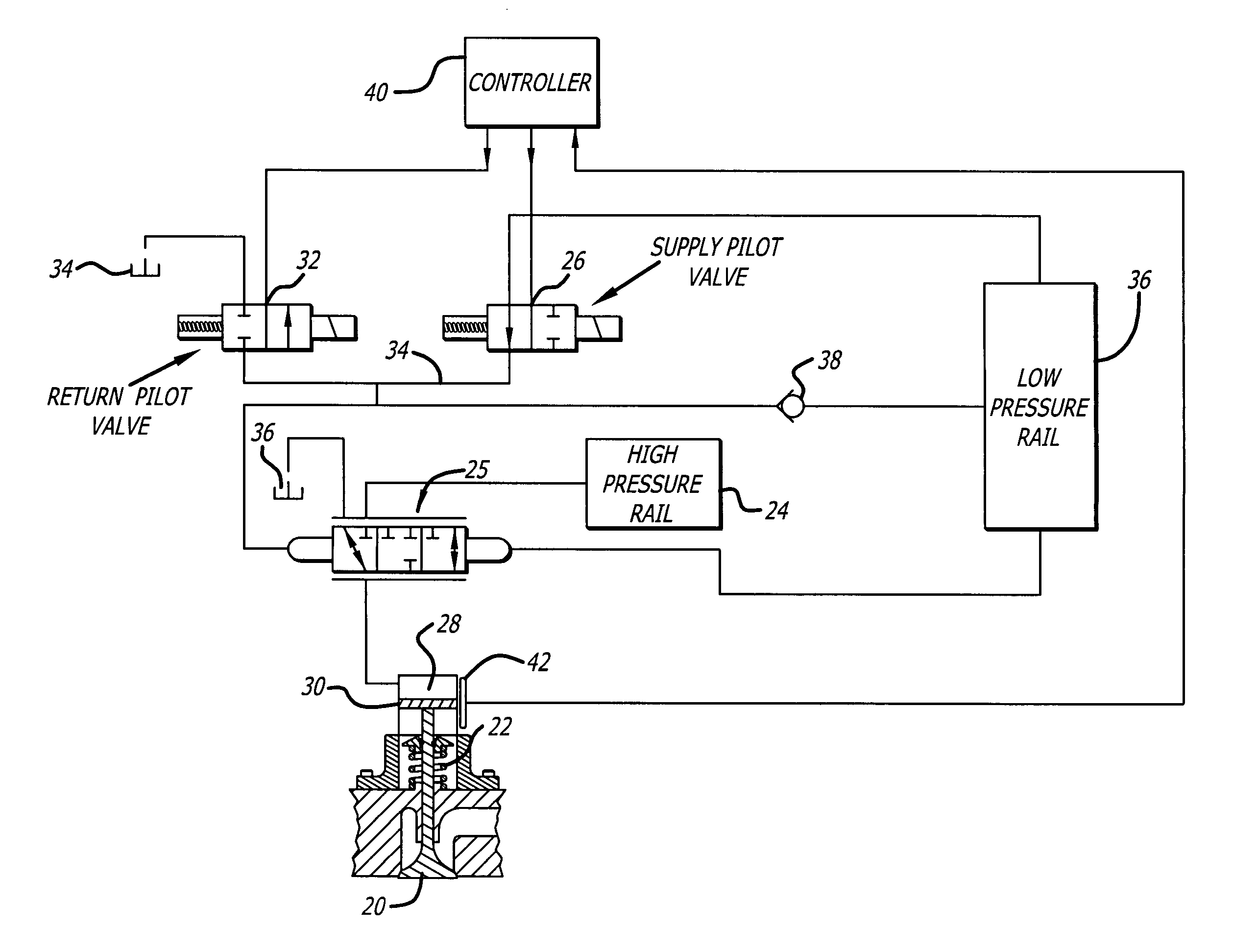
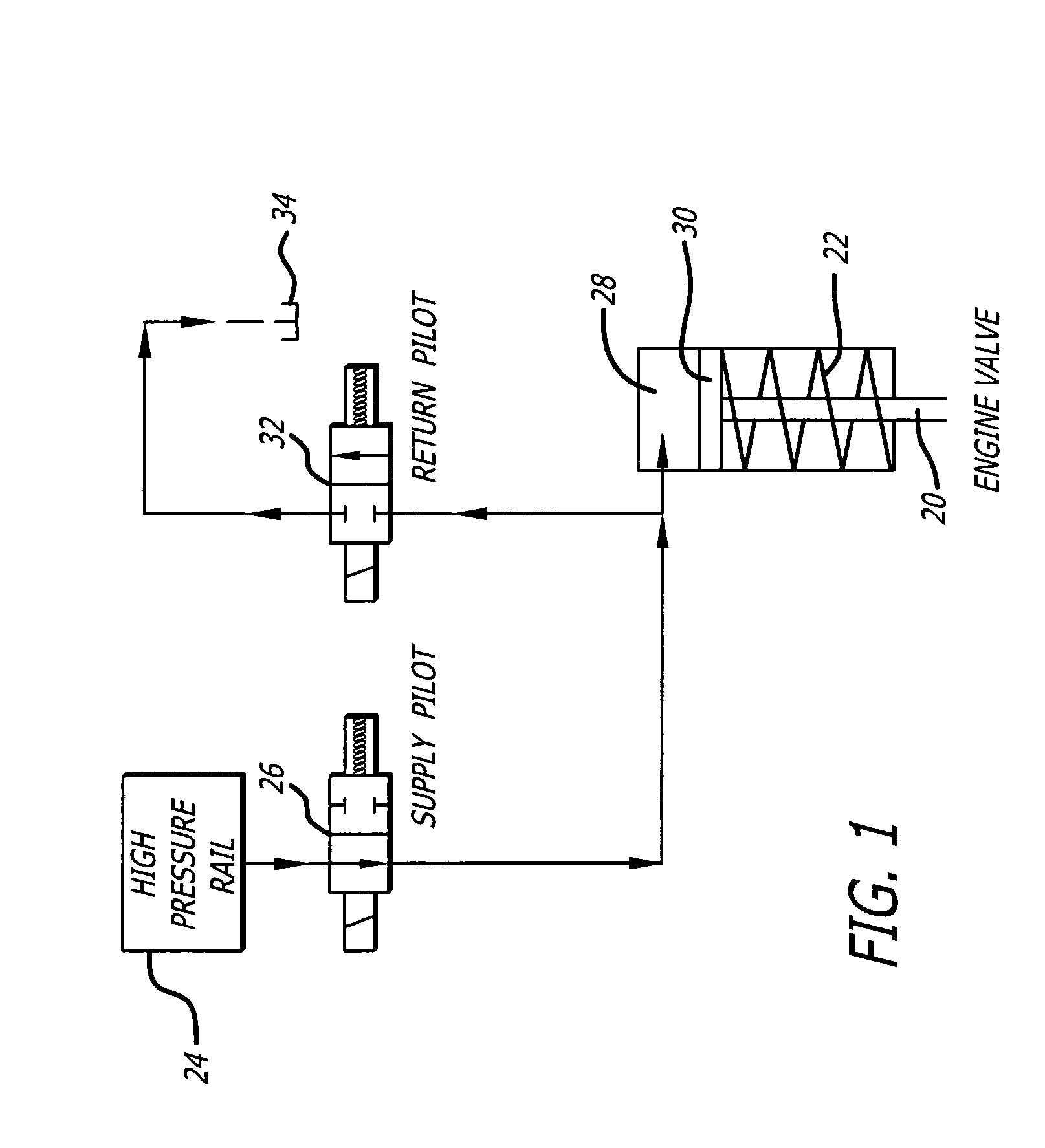
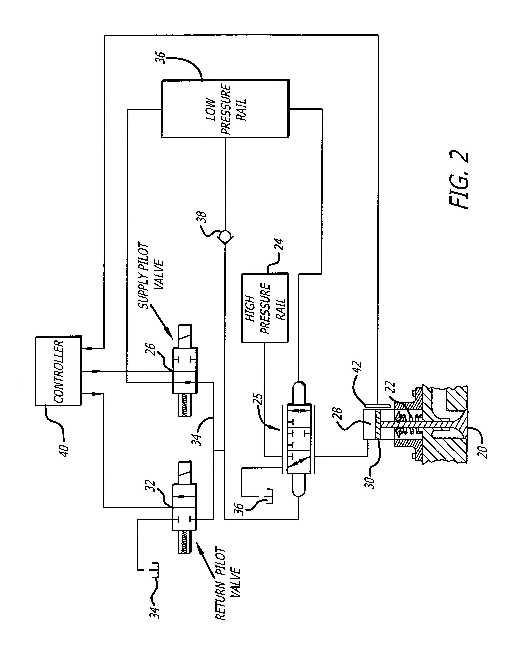
  • Hydraulic valve actuation methods and apparatus
  • Hydraulic valve actuation methods and apparatus
  • Hydraulic valve actuation methods and apparatus

Examples


Embodiment Construction

[0013]In a typical piston-type internal combustion engine having intake and exhaust valves, each with an engine valve return spring, the engine valve return springs are preloaded to provide the desired engine valve closing forces. These forces generally include a predetermined minimum force to hold the engine valve closed to prevent leakage, particularly after the compression and the power strokes. Also, in cam driven engine valve systems, the engine valve return springs must provide adequate forces throughout the engine valve motion to assure that the engine valve and engine valve drive system (cam follower, etc.) actually follow the profile defined by the cam, and do not float free of the cam at high engine speeds, as floating causes loss of power and can damage or destroy the engine valve or parts of the engine valve drive system.

[0014]In hydraulic engine valve drive systems, the engine valve return spring requirements are similar, as the required spring force to hold an engine v...


PUM


Abstract

Hydraulic engine valve actuation methods for internal combustion engines having improved energy efficiency. In hydraulic engine valve operating systems using spring returns for valve closure, the spring force is a minimum when the valve is closed and a maximum at the maximum lift. The present invention takes advantage of this difference by using a valve opening hydraulic force which is greater than the spring force when the valve is closed and less than the spring force when the valve is open at its maximum lift. The valve actuator is controlled to allow the valve, when opening, to overshoot the equilibrium condition. During the overshoot, the hydraulic actuator backfills with actuating fluid at it normal actuating pressure. When the valve velocity decays to zero or near zero, the flow of hydraulic fluid to (and from) the valve actuator may be cut off, capturing the valve substantially at the overshoot position.

Description

CROSS-REFERENCE TO RELATED APPLICATION[0001]This application claims the benefit of U.S. Provisional Patent Application No. 60 / 395,370 filed Jul. 11, 2002.BACKGROUND OF THE INVENTION[0002]1. Field of the Invention[0003]The present invention relates to the field of hydraulic intake and exhaust valve actuation methods and apparatus for internal combustion engines.[0004]2. Prior Art[0005]At the present time, piston-type internal combustion engines of interest to the present invention are widely used in automobiles, trucks, buses and various other mobile and stationary power systems. Such engines include the common gasoline and diesel engines, as well as similar engines operating from alternative fuels such as liquid natural gas. These engines commonly utilize intake and exhaust valves that are spring loaded to the closed position and which are directly or indirectly opened at appropriate times by a camshaft mechanically driven from the engine crankshaft.[0006]Camshaft actuation of engin...

Claims


Application Information

Patent Timeline
Patent Type & Authority Patents(United States)
IPC IPC(8): F16K21/04F01L9/10
CPCF01L9/02F01L9/10
Inventor LAMMERT, MICHAEL P.RAIMAO, MIGUEL ANGELOGIORDANO, DANIEL D.TURNER, CHRISTOPHER WAYNEBALTON, CHRISTOPHER STEVENSBABBITT, GUY ROBERT
Owner STURMAN INDS
Learn More