Four position gate latch assembly

Inactive Publication Date: 2006-04-04
RAOULT PHILIPPE P
View PDF54 Cites 53 Cited by
  • Summary
  • Abstract
  • Description
  • Claims
  • Application Information

AI Technical Summary

Benefits of technology

[0009]Latches for interior and exterior gates, and particularly gates on fences, have been utilized for centuries in one form or another. At the present time a gravity type gate latch that is self-fastening is exceptionally popular and used on a great number of gates throughout the United States. A conventional gate latch utilizes a pivoting cam latch that is enclosed within a stamped and formed sheet metal housing and is usually fastened with screws to a stationary portion of the fence. The gate latch is sturdy and robust and will last for a considerable duration as it utilizes a heavy metal structure and is normally plated to resist corrosion. Therefore, the primary object of the invention is to expand the use of this existing gate latch design without affecting its original function by using a different striker bar that is movable to produce additional capabilities. The invention may be used in four different ways that expand the functional operation of an industry standard latch. First, the gate latch retains its conventional operation which allows the gate to be opened from the outside by pulling on a cord, cable or chain that pivots a cam latch away from the striker bar. Second, the invention permits a locked position, with a locking bolt penetrating an existing padlock hole in the gate latch. Third, an unlatched position permits the gate to swing inward on the gate latch side without interference. Fourth, a free-swinging position permits the gate to pivot in both directions.
[0010]An important object of the invention is that the most difficult manufacturing element is the gravity gate latch which is already in production in vast numbers, therefore using economies of numbers the initial cost can be maintained at a low level.
[0011]Another object of the invention is that the gate latch and bracket are extremely simple to produce with standard production equipment.
[0012]Still another object of the invention is the ease of operation, as one simply extends the locking bolt into the hole in the gate latch to lock the latch. Additionally, the position of the latch striker bar is easily understood when visually observed.
[0013]Yet another object of the invention is the ease of installation as both the gate latch and the latch bracket are easily mounted with four screws in a conventional manner.

Problems solved by technology

In most cases, the latches are rather elaborate and require many individual components, thus making them expensive and complex.

Method used


Image

  • Four position gate latch assembly
  • Four position gate latch assembly
  • Four position gate latch assembly

Examples


Embodiment Construction

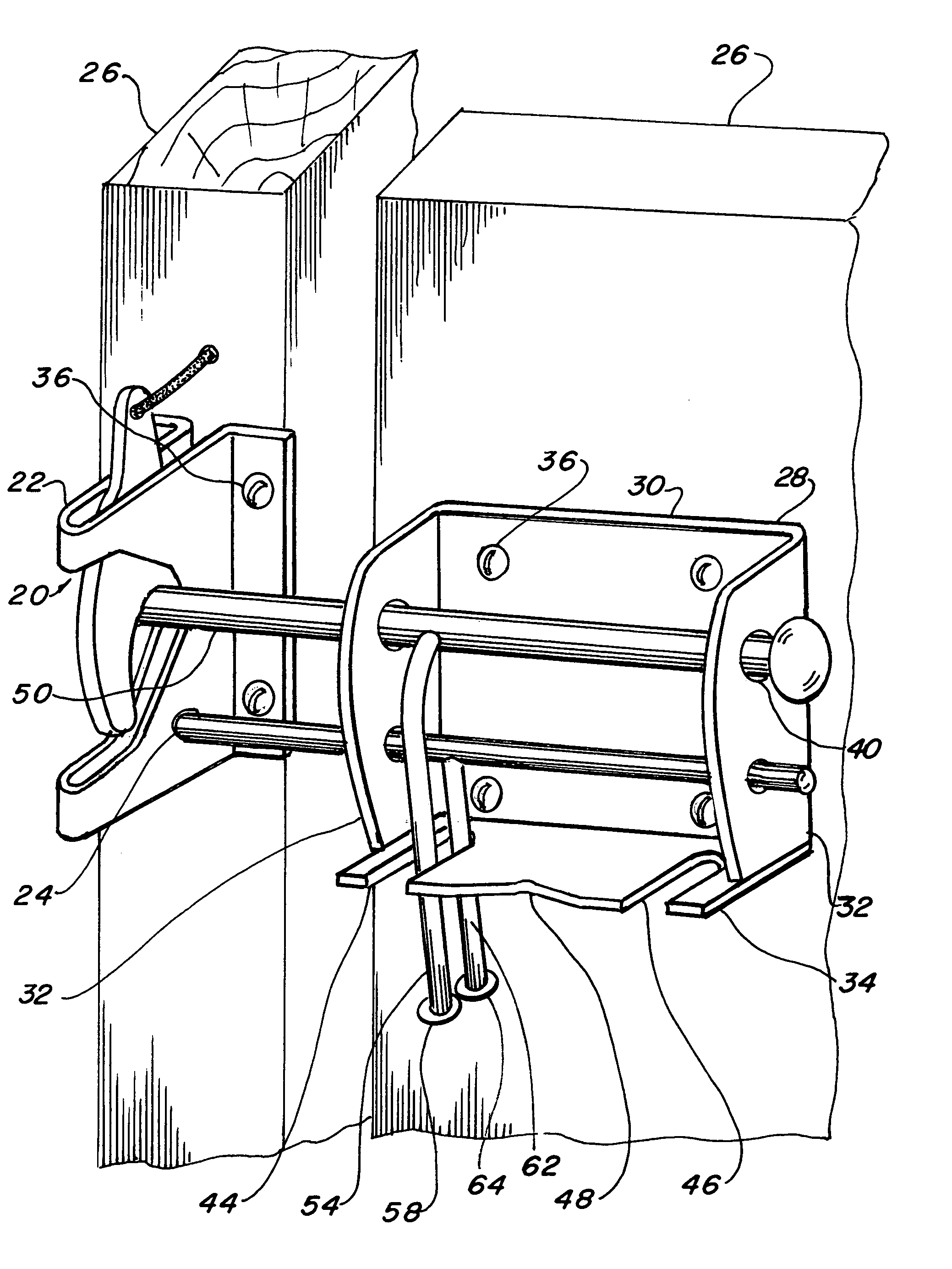
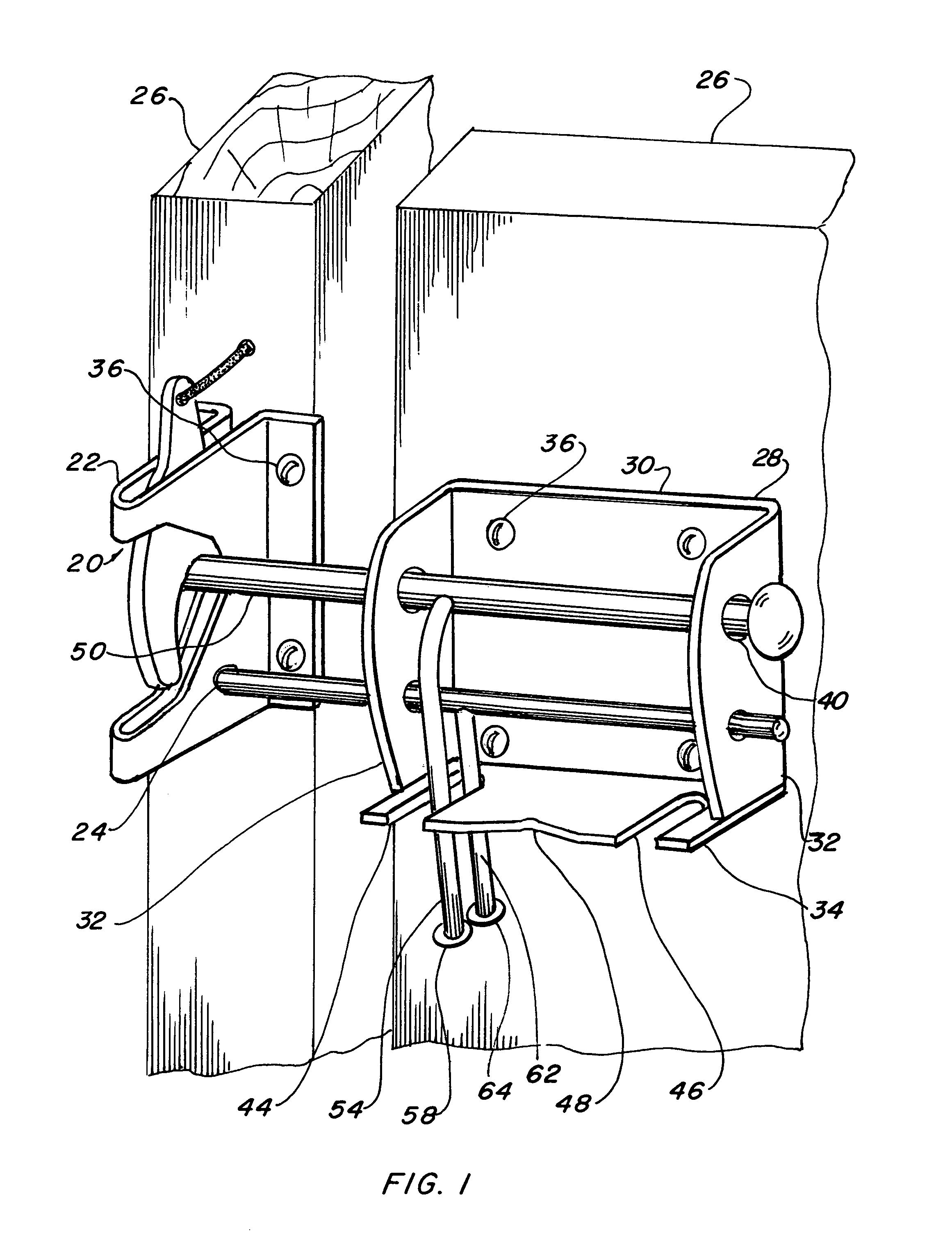
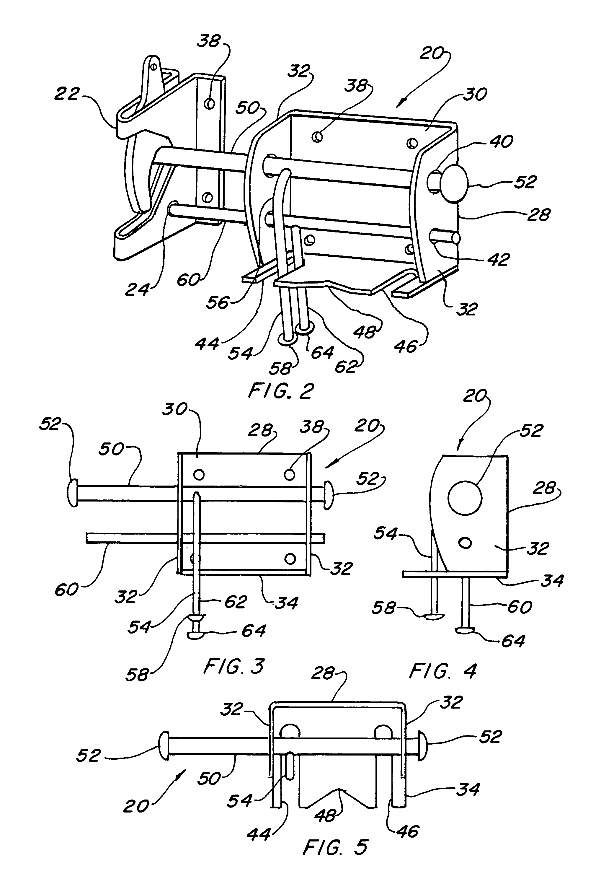
[0040]The best mode for carrying out the invention is presented in terms of a preferred embodiment. The preferred embodiment as shown in FIGS. 1 through 25, is comprised of a four position gate latch 20, which is preferably made of metal and incorporates a self fastening gravity gate latch 22 having a padlock hole 24 therethrougth. The padlock hole 24 is commonly included in some models of the latch 20 or the latch may be modified by adding the hole after assembly. The gate latch 22 is fastened to one face of a gate 26, as shown in FIG. 1, and consists of a pivoting cam latch enveloped within a flanged housing.

[0041]A gate latch bracket 28 is attached to the gate 26, preferably on the pivoting side in parallel alignment with the gate latch 22. The gate latch bracket 28 is formed from sheet metal and is configured to include a base 30 with a pair of opposed outward-extending vertical flanges 32 and an outward-extending bottom flange 34. The bracket 28 is fastened to the gate 26 with ...


PUM


Abstract

A four position gate latch (20) that is used to fasten and lock a gate. The gate latch includes a self fastening gravity gate latch (22) that is fastened to one face of the gate. A gate latch bracket (28) is fastened to the gate on an opposed face, mating with said gate latch. A latch striker bar slideably extends from the bracket such that the striker bar interfaces with the gate latch and links the gate portions together. A locking bolt (60) slideably extends though the bracket, allowing it to interface with the gate latch and provide positive locking capabilities. The gate latch is capable of being placed in a self fastening gravity gate latch conventional position, a locked position with the locking bolt penetrating a padlock hole, an unlatched position that permits the gate to swing inward on the gate latch side without interference, and a free-swinging position that permits the gate to pivot in both directions.

Description

TECHNICAL FIELD[0001]The invention relates to gate latches in general, and more specifically to a gate latch utilizing a self-fastening gravity gate latch in combination with a bracket having a striker bar and a locking bolt, which permits operation in four separate positions.BACKGROUND ART[0002]Previously, many types of gate latches have been used to provide an effective means of securing gates, specifically wooden fence gates and the like. In most cases, the latches are rather elaborate and require many individual components, thus making them expensive and complex.[0003]A search of the prior art did not disclose any patents that possess the novelty of the instant invention, however the following U.S. patents are considered related:[0004]Patent NumberInventorIssue Date3,953,064Mc HenryApr. 27, 19764,643,469Johnston et al.Feb. 17, 19874,690,440RogersSep. 1, 19875,452,544Weathington, Sr.Sep. 26, 1995[0005]Mc Henry in U.S. Pat. No. 3,953,064 teaches a gate latch suitable for sliding a...

Claims


Application Information

Patent Timeline
IPC IPC(8): E05C5/00
CPCA01K1/0017E05B65/0007E05B15/0093Y10S292/63Y10S292/29Y10T292/0886Y10T292/0887Y10T292/089Y10T292/0891Y10T292/1022Y10T292/1023Y10T292/379Y10T292/696
Inventor RAOULT, PHILIPPE P.
Owner RAOULT PHILIPPE P
Why Eureka
Try Eureka