
Vehicle steering damper, steering damper kit for motorcycle, and motorcycle incorporating same

a technology for steering dampers and motorcycles, which is applied in the direction of shock absorbers, steering devices, cycle equipments, etc., can solve the problems of difficult to find space for actuators, actuators require a comparatively large mounting space, and small space available, so as to achieve effective utilization of the gap

Inactive Publication Date: 2006-04-04
HONDA MOTOR CO LTD
View PDF13 Cites 20 Cited by
  • Summary
  • Abstract
  • Description
  • Claims
  • Application Information

AI Technical Summary

Benefits of technology

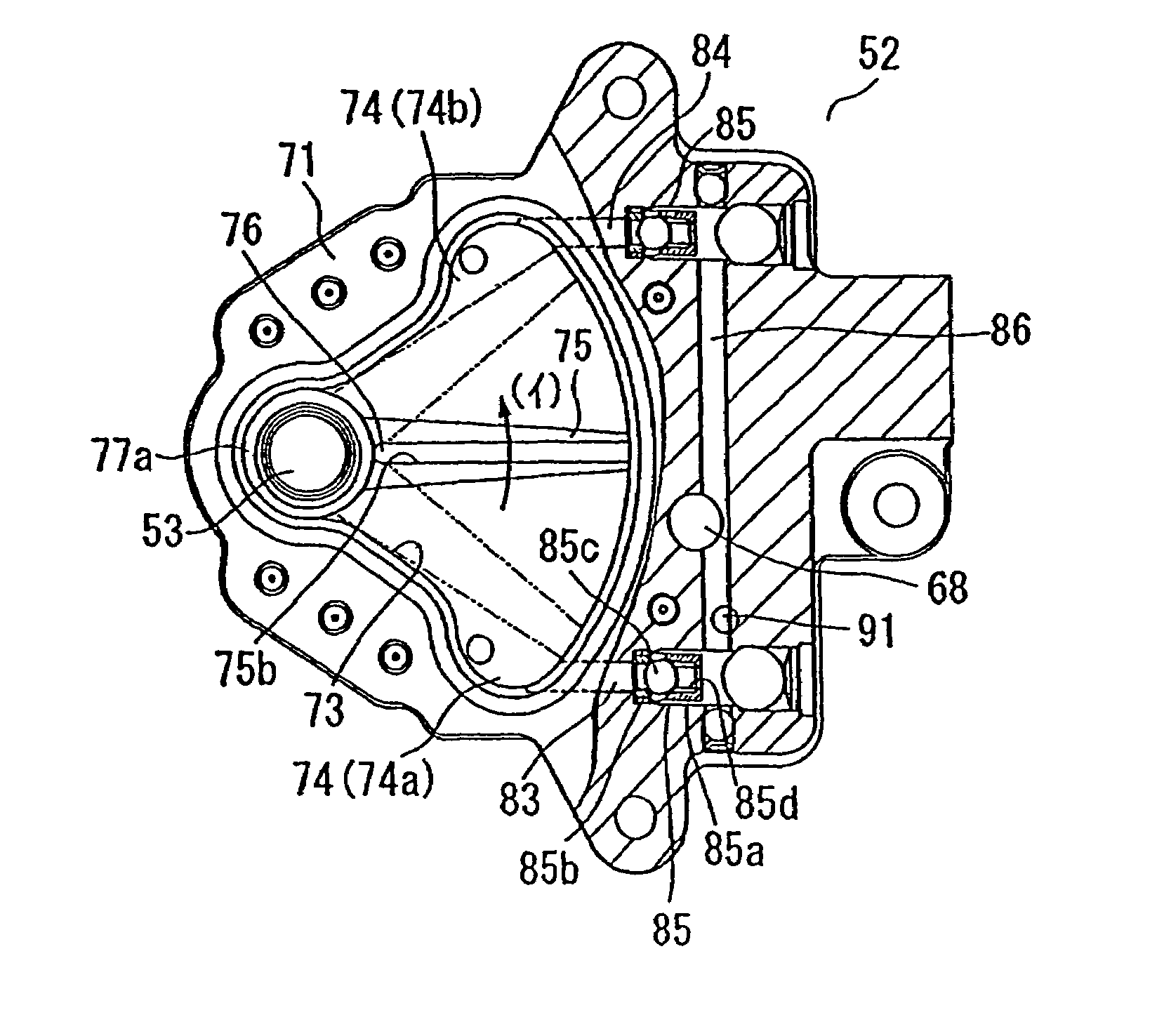
[0016]Usually, in a motorcycle, a gap is formed between a top bridge and a fuel tank disposed rearwardly of the top bridge. In the present invention, however, in order to effectively utilize the gap, the housing is disposed such that it extends rearwardly beyond the top bridge, and besides, the actuator for the hydraulic pressure control valve is disposed below the extension of the housing which extends rearwardly farther than the top bridge. Consequently, effective utilization of the gap between the top bridge and the fuel tank can be anticipated. Further, the actuator does not project upwardly from the housing, and interference between the actuator and a movable member in the proximity of the top bridge can be prevented.

Problems solved by technology

The actuator requires a comparatively large mounting space, however, the position above the top bridge, where the steering damper of the rotary type described above is disposed, only has a very small space available, in which a fuel tank is disposed rearwardly in a crowded relationship and an ignition switch is disposed forwardly.
Thus, it is difficult to find space for the actuator, which generally takes up a large mounting space, in such a place which is narrow and small and in which various movable parts are disposed.

Method used


Image

  • Vehicle steering damper, steering damper kit for motorcycle, and motorcycle incorporating same
  • Vehicle steering damper, steering damper kit for motorcycle, and motorcycle incorporating same
  • Vehicle steering damper, steering damper kit for motorcycle, and motorcycle incorporating same

Examples


Embodiment Construction

[0036]Referring now to the drawings, a motorcycle 1 includes a vehicle body frame 2 substantially at the center thereof, as shown in FIG. 1. A head pipe 3 is provided at a front end of the vehicle body frame 2, and a front fork 5 is supported on the head pipe 3 through a steering stem 6. The front fork 5 rotatably supports a front wheel 4 at the lower end thereof.

[0037]The vehicle body frame 2 also includes a main frame 7, which extends obliquely rearwardly and downwardly from the head pipe 3. The main frame 7 is bifurcated and forks to the left and right as it extends behind the head pipe 3. The main frame 7 further extends rearwardly through a bent portion thereof, as shown. A pivot connection 8 is provided at a front end portion of a substantially central portion of the portion of the main frame 7 which extends downwardly, and a rear fork 10 is supported by the pivot connection 8 for rocking motion.

[0038]A rear wheel 9 is supported on the back of the rear fork 10. Further, an int...


PUM


Abstract

A steering damper in a motorcycle includes a vane partitioning a chamber in a damper housing into two oil chambers, wherein hydraulic fluid flows between the two chambers to generate attenuating force. The steering damper also includes a damper shaft connected to the vane and supporting the vane for rocking motion with respect to the housing, and a hydraulic pressure control valve. The housing is attached to a head pipe, and the damper shaft is attached to a steering system. When the head pipe is to be attached to the housing, the housing is extended rearwardly behind a top bridge, and a linear solenoid for driving and controlling the hydraulic pressure control valve is attached to the housing and disposed below the extension thereof.

Description

CROSS-REFERENCE TO RELATED APPLICATIONS[0001]The present invention claims priority under 35 USC 119 based on Japanese patent applications 2003-079156 and 2003-079158, both filed Mar. 20, 2003.BACKGROUND OF THE INVENTION[0002]1. Field of the Invention[0003]The present invention relates to vehicular steering dampers and related hardware. More particularly, the present invention relates to steering dampers and related attaching structure for a motorcycle, and to a motorcycle incorporating the novel steering damper.[0004]2. Description of the Background Art[0005]As a conventional attaching structure for a steering damper in a motorcycle, a steering damper attaching structure is known which includes a rotary-type steering damper wherein, upon rocking motion of a vane which partitions an oil chamber in a housing into two oil chambers, working fluid flows between the two oil chambers to generate attenuating force. (see, for example, Japanese Patent Laid-Open No. 2002-302085 (left column of...

Claims


Application Information

Patent Timeline
IPC IPC(8): F16D57/02F16F9/14B62K21/08
CPCF16F9/145B62K21/08
Inventor YAMADA, SHINICHISAKAI, KIYOTAKANANRI, TAKEHIKOWAKABAYASHI, TAKESHI
Owner HONDA MOTOR CO LTD
Learn More