
Fluorescent metal sensors, and methods of making and using the same

a metal sensor and fluorescence technology, applied in the field of fluorescence metal sensors, can solve the problems of significant changes in fluorescent properties observed, and achieve the effect of high quantum yield

Inactive Publication Date: 2006-03-28
MASSACHUSETTS INST OF TECH
View PDF8 Cites 11 Cited by
  • Summary
  • Abstract
  • Description
  • Claims
  • Application Information

AI Technical Summary

Benefits of technology

[0004]The feasibility of using fluorescence technology for a particular application is often limited by the availability of an appropriate fluorescent sensor. There are a number of features that are desirable in fluorescent sensors, some of which may or may not be present in any particular sensor. First, fluorescent sensors should produce a perceptible change in fluorescence upon binding a desired analyte. Second, fluorescent sensors should selectively bind a particular analyte. Third, to allow concentration changes to be monitored, fluorescent sensors should have a Kd near the median concentration of the species under investigation. Fourth, fluorescent sensors, especially when used intracellularly, should produce a signal with a high quantum yield. Fifth, the wavelengths of both the light used to excite the fluorescent molecule (excitation wavelengths) and of the emitted light (emission wavelengths) are often important. If possible, for intracellular use, a fluorescent sensor should have excitation wavelengths exceeding 340 nm to permit use with glass microscope objectives and prevent UV-induced cell damage, and possess emission wavelengths approaching 500 nm to avoid autofluorescence from native substances in the cell and allow use with typical fluorescence microscopy optical filter sets. Finally, ideal sensors should allow for passive and irreversible loading into cells.

Problems solved by technology

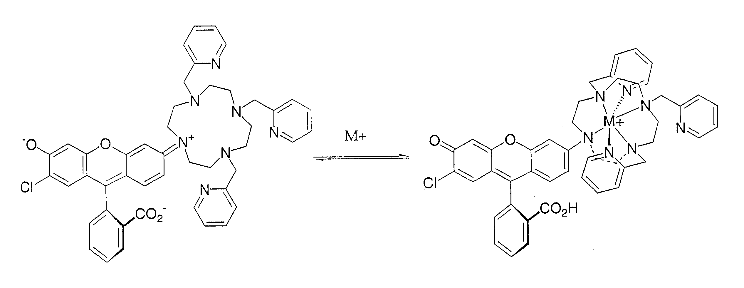
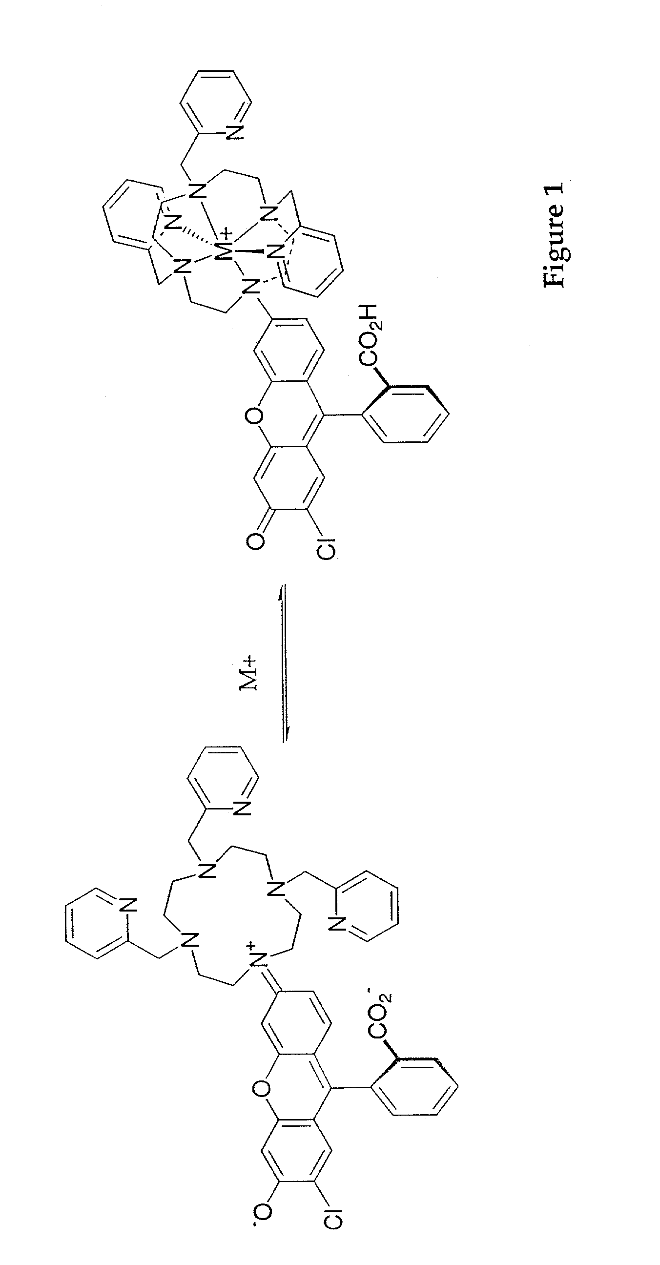
Further, certain of the subject compositions are expected to have properties akin to either rhodamine or fluorescein depending on whether they are complexed with a metal ion, which should result in significant changes to the fluorescent properties observed.

Method used


Image

  • Fluorescent metal sensors, and methods of making and using the same
  • Fluorescent metal sensors, and methods of making and using the same
  • Fluorescent metal sensors, and methods of making and using the same

Examples


Embodiment Construction

I. Definitions

[0034]For convenience, before further description of the present invention, certain terms employed in the specification, examples and appended claims are collected here. These definitions should be read in light of the remainder of the disclosure and understood as by a person of skill in the art.

[0035]The articles “a” and “an” are used herein to refer to one or to more than one (i.e., to at least one) of the grammatical object of the article. By way of example, “an element” means one element or more than one element.

[0036]The terms “Lewis base” and “Lewis basic” are art-recognized and generally include a chemical moiety, a structural fragment or substituent capable of donating a pair of electrons under certain conditions. It may be possible to characterize a Lewis base as donating a single electron in certain complexes, depending on the identity of the Lewis base and the metal ion, but for most purposes, however, a Lewis base is best understood as a two electron donor....


PUM

PropertyMeasurementUnit
emission wavelengthsaaaaaaaaaa
excitation wavelengthsaaaaaaaaaa
pKaaaaaaaaaaa

Abstract

The present invention is directed, in part, to fluorescent metal sensors for detecting metal ions, and methods of making and using the same.

Description

RELATED APPLICATION INFORMATION[0001]This application claims the benefit of priority under 35 U.S.C. section 119(e) to Provisional Patent Application No. 60 / 284,700, filed Apr. 17, 2001. Such provisional patent application is hereby incorporated by reference in its entirety.GOVERNMENT SUPPORT[0002]The subject invention was made in part with support from the U.S. Government under a grant awarded by the National Cancer Institute, a National Cancer Institute National Research Service Award, and Grant Number 1-R01-GM65519-01 awarded by the NIH. Accordingly, the U.S. Government has certain rights in this invention.INTRODUCTIONI. Fluorescent Sensors[0003]Fluorescence technology has revolutionized cell biology and many areas of biochemistry. In certain instances, fluorescent molecules may be used to trace molecular and physiological events in living cells. Certain sensitive and quantitative fluorescence detection devices have made fluorescence measurements an ideal readout for in vitro bio...

Claims


Application Information

Patent Timeline
Patent Type & Authority Patents(United States)
IPC IPC(8): G01N33/20G01N31/22G01N33/84
CPCG01N33/84G01N31/22
Inventor LIPPARD, STEPHEN J.BURDETTE, SHAWN
Owner MASSACHUSETTS INST OF TECH
Learn More