Multi-turn angle transducer

a transducer and multi-turn technology, applied in the direction of gearing, instruments, hoisting equipment, etc., can solve the problems of occupying a large space, requiring a much larger footprint, and reed contacts subject to mechanical wear, so as to achieve high rotational speed, large input shaft diameter, and high number of rotations

Active Publication Date: 2006-03-28
SICK STEGMANN
View PDF20 Cites 35 Cited by
  • Summary
  • Abstract
  • Description
  • Claims
  • Application Information

AI Technical Summary

Benefits of technology

[0007]It is an object of the present invention to develop a multi-turn shaft encoder of compact construction and with relatively few multi-turn stages, which is capable of measuring a high number of rotations at high rotational speed and / or large diameter of the input shaft.

Problems solved by technology

Such so-called counting multi-turn shaft encoders, however, require a backup battery for counting when power is off.
The reed contacts are subject to mechanical wear and therefore have only a limited lifetime.
Moreover, the battery takes up space and must therefore be positioned outside the sensor housing when the size of the multi-turn shaft encoders must be kept small.
However, this requires a much larger footprint.
Accordingly, a high rotational speed of the input shaft results in greater wear of the gears which leads to a reduced lifetime for the multi-turn angle measuring device.

Method used


Image

  • Multi-turn angle transducer
  • Multi-turn angle transducer
  • Multi-turn angle transducer

Examples


Embodiment Construction

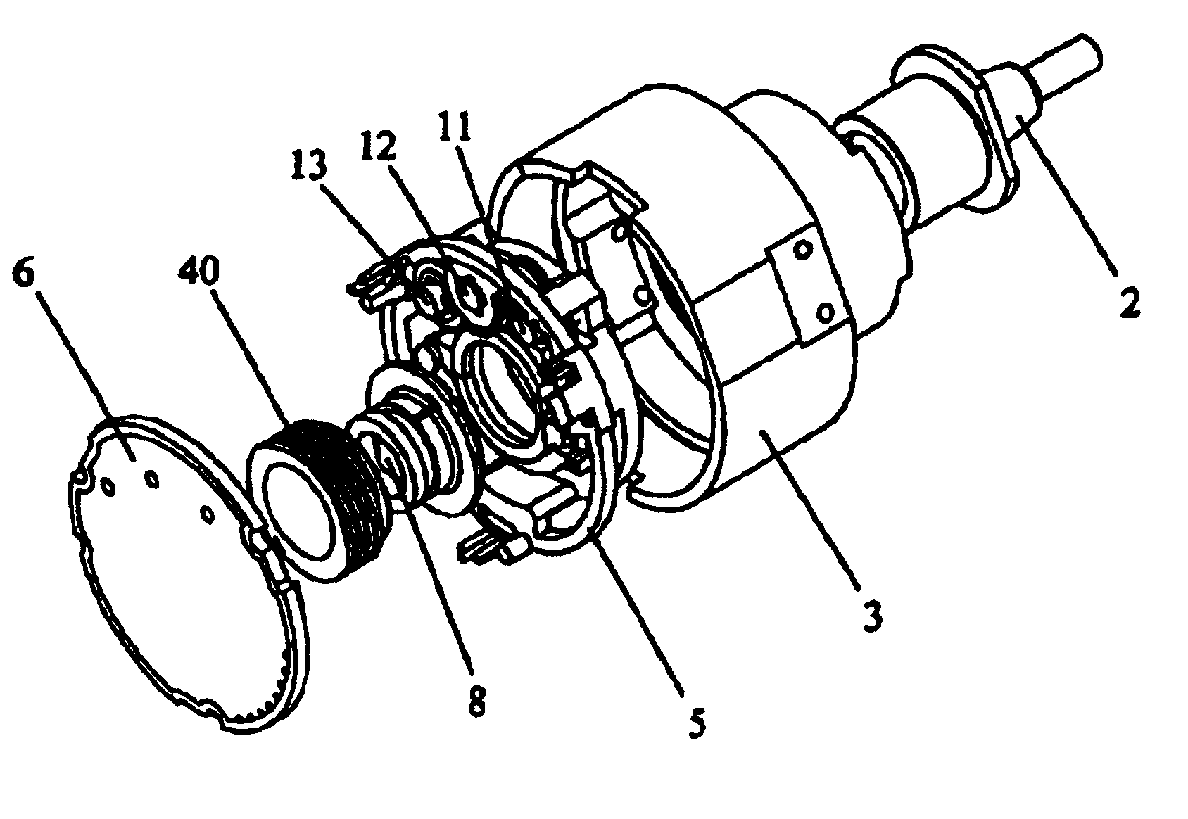
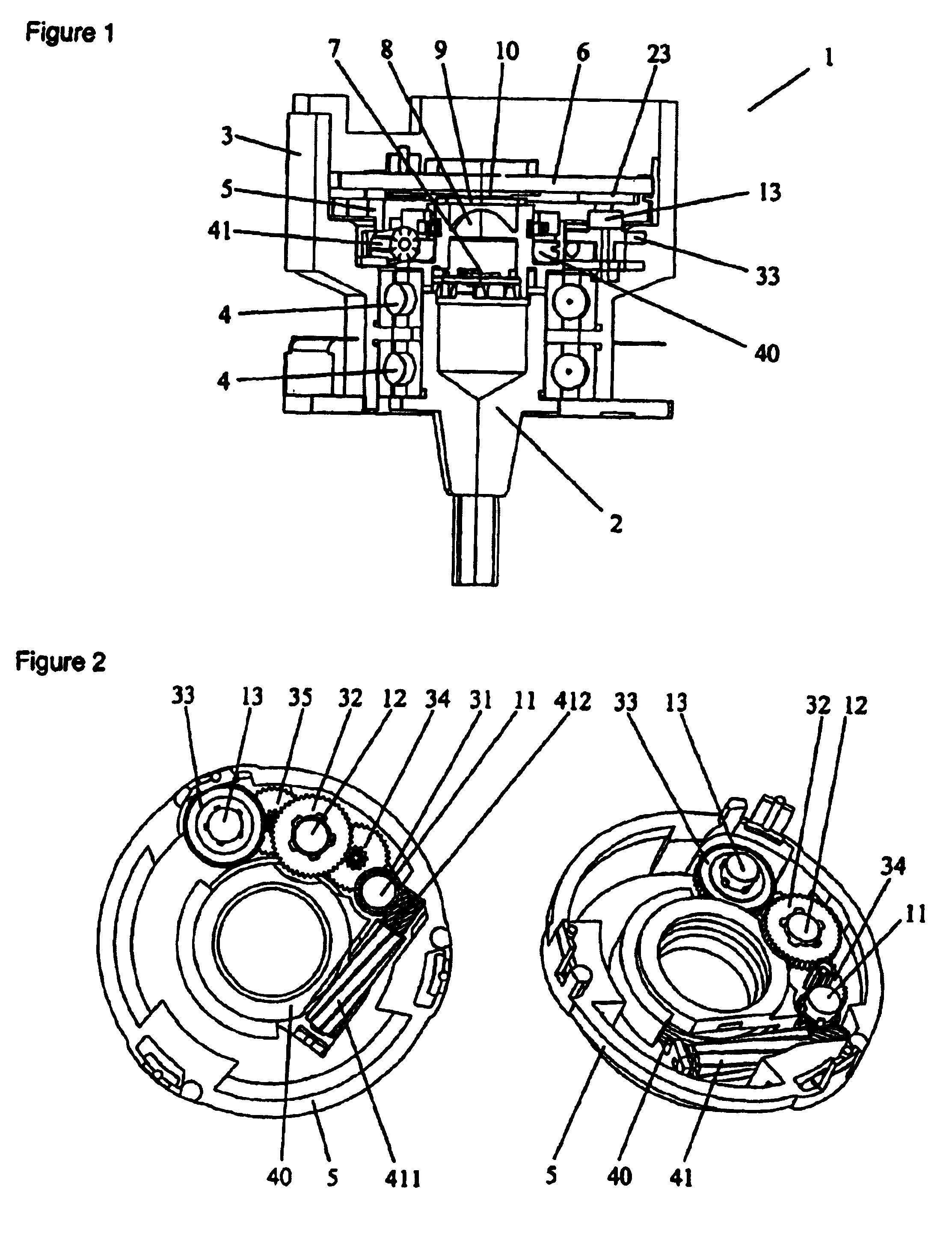
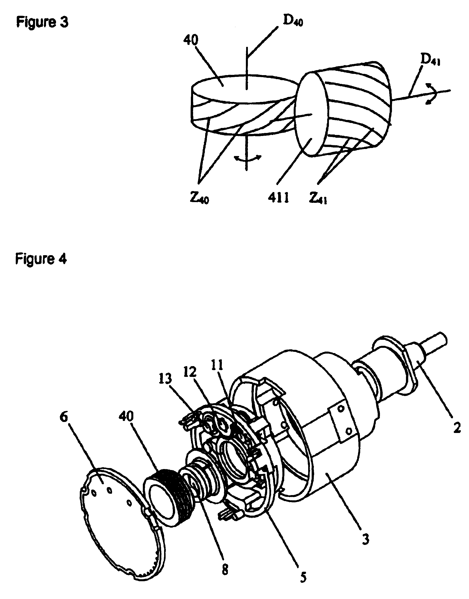
[0024]A multi-turn angle measuring device 1 comprises a few modular components. It has a housing 3, an input shaft 2, a code disk 9 connected to the latter, a multi-turn transmission unit 5 and a circuit board 6 on which are arranged the scanning units for detection of the code disk 9, as well as the multi-turn dimensional standards 11, 12, 13.

[0025]In order to measure the absolute angular position of the input shaft 2 over one turn, the code disk 9 is illuminated by a phototransmitter 7 and detected by a scanning unit 10. The phototransmitter preferably is a light-emitting diode (LED).

[0026]The optical code disk 9 carries an absolute binary code, preferably a gray code or a sequential code, which can be formed by light / dark windows. For transmissive sampling, the encoding can be in the form of a thin, photolithographically structured chromium layer on a glass substrate. In addition, an incremental code track can be arranged on the code disk 9, consisting of the highest possible num...


PUM


Abstract

A multiturn angle measuring device (1) with a first dimensional standard (9) that is non-rotatably connected to an input shaft (2) and which is sampled by a first scanning unit (10) to determine the angular position of the input shaft. Additional dimensional standards (11, 12, 13) measure the number of turns of the input shaft (2) and are arranged in parallel to each other. The rotational speed of each additional dimensional standard (11, 12, 13) is reduced by means of a reduction gearing from the preceding dimensional standard (9, 11, 12). A scanning device (21, 22, 23) for the sampling of each dimensional standard (11, 12, 13) is arranged on a circuit board (6). To provide a multiturn shaft encoder able to measure a high number of turns, even at high rotational speeds and/or large diameter input shafts, with compact construction and comparatively few multiturn stages, the input drive gear (40) fixed to the input shaft (2) and the first driven transmission gear (41) have axes of rotation (D40, D41) that are not parallel to each other. The flanks of the teeth (Z40, Z41) of the input drive gear (40) and of the wheel (411) of the first driven transmission gear (41) are not parallel to the axes of rotation (D40, D41) of the respective gears (40, 41), and the number of teeth (Z40) of the input gear (40) is smaller than the number of teeth (Z41) of the wheel (411) of the first transmission gear (41). The following transmission gears are again arranged parallel to the input shaft, and the drive pinion (412) of the first transmission gear (41) and the driven wheel of the second transmission gear (31) have helical gears.

Description

BACKGROUND OF THE INVENTION[0001]Multi-turn angle measuring devices are electromechanical sensors which detect absolutely several revolutions; i.e., within the resolution of the device the distinct angular position is always available even after the device has been switched on and completed several revolutions. Such angle measuring devices are used to measure shafts and axles and for positioning and control of electric motors in industry, especially in connection with manufacturing and handling machinery.[0002]Multi-turn shaft encoders preferably have a compact construction and a high number of distinctly detectable turns. DE 28 17 172 C2 describes a shaft encoder which has a compact footprint in that the multi-turn dimensional standards are driven by a spur reduction gear and lie within the circumferential region of the single code disk. In this case, the sensors for detection of the multi-turn and the single-turn rotational movements, or scales, are arranged on different circuit b...

Claims


Application Information

Patent Timeline
Patent Type & Authority Patents(United States)
IPC IPC(8): G01B7/30G01D5/34G01D5/245F16H1/12F16H37/04F16H55/22G01D5/04G01D5/14G01D5/16G01D5/36
CPCG01D5/145G01D5/04G01D2205/26
Inventor STOBBE, WILLIBALD
Owner SICK STEGMANN
Why Eureka
Try Eureka