Method for commutating an electronically commutated motor and motor for carrying out said method

a technology of electronically commutated motors and motors, which is applied in the direction of electronic commutators, synchronous motor starters, rotary current collectors, etc., can solve the problems of “wasted power output” and too expensive for many applications, and achieve reliable commutation, simple and inexpensive configuration, and increased power output of such a motor.

Inactive Publication Date: 2006-03-21
EBM PAPST ST GEORGEN & -
View PDF9 Cites 2 Cited by
  • Summary
  • Abstract
  • Description
  • Claims
  • Application Information

AI Technical Summary

Benefits of technology

[0007]A comparator is thus associated with each MOSFET of the bridge. When one of these MOSFETs is to be switched off, this occurs directly by way of its comparator. When one of these MOSFETs is to be switched on, the associated comparator then monitors the gate potential of the MOSFET that is to be switched off, i.e., in practice, its source-gate voltage. A reliable signal is thereby obtained as to when that MOSFET is blocked, and only then is the MOSFET that is to be switched on, switched on. It is very advantageous that with this method, the comparators are utilized differently depending on their instantaneous function (switching off or switching on), i.e. in one case as an amplifier, in the other as a comparator. The power output of such a motor can moreover be increased in many cases by optimizing the current off-time.
[0008]The stated object is achieved in a different fashion by controlling current flow through the winding phase using a p-channel MOSFET between the positive lead and the winding, and an n-channel MOSFET between the winding and the negative lead, with each MOSFET being controlled by a respective comparator, one of the comparators responding to the rotor position signal, and the other of the comparators responding to a gate voltage of the transistor being switched off. A motor of this kind combines reliable commutation with a very simple and inexpensive configuration, good power output, quiet operation, and a long service life for the MOSFETs in the full bridge circuit.

Problems solved by technology

A prerequisite for this, however, is that a microprocessor be used, and this is too expensive for many applications.
The current off-time of, for example, 50 μs must furthermore be made so long that is sufficiently long under all operating conditions, with the result that, especially at higher rotation speeds, power output may be “wasted” because the current off-time could be shorter under many operating conditions.

Method used


Image

  • Method for commutating an electronically commutated motor and motor for carrying out said method
  • Method for commutating an electronically commutated motor and motor for carrying out said method
  • Method for commutating an electronically commutated motor and motor for carrying out said method

Examples


Embodiment Construction

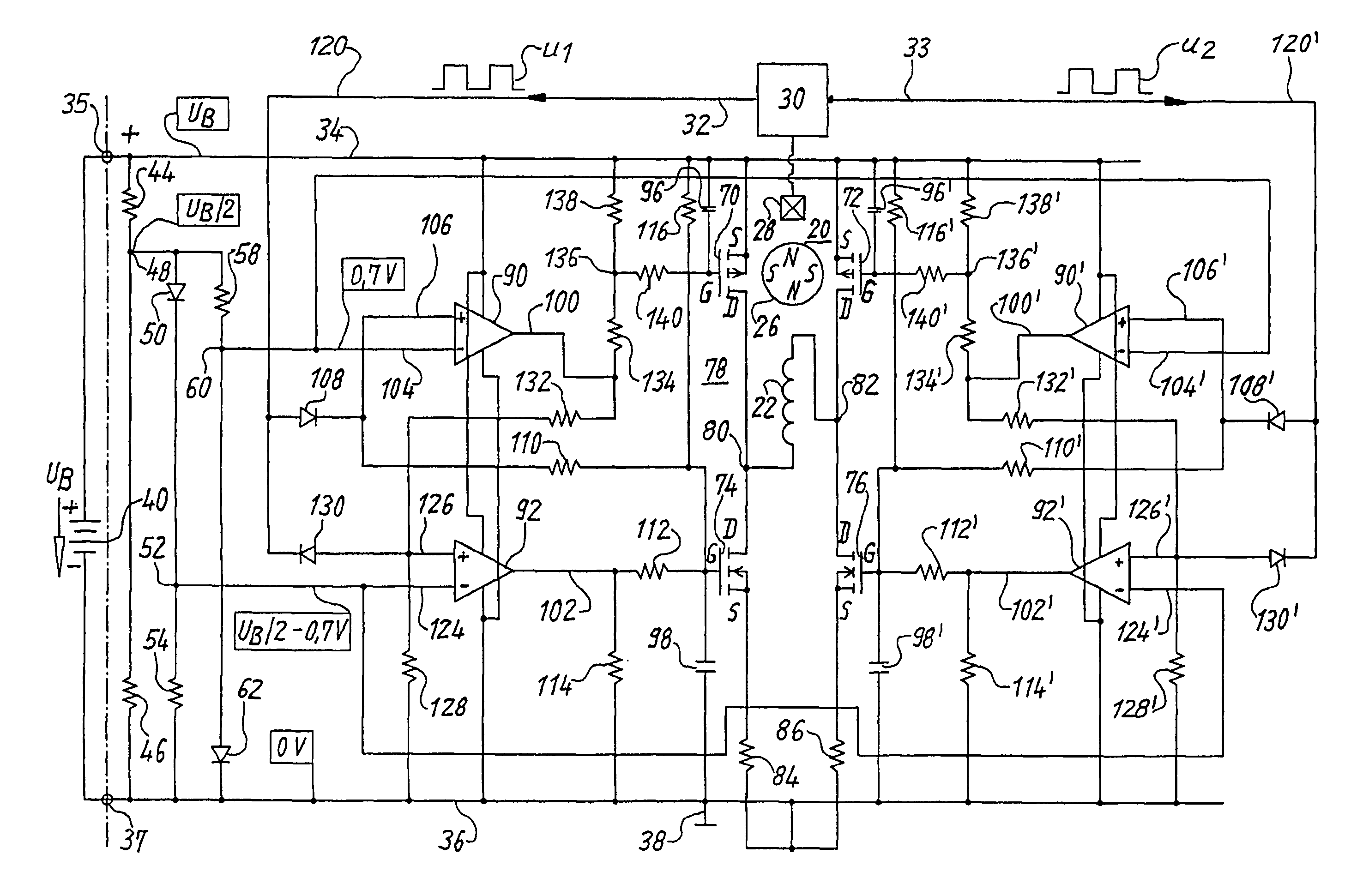
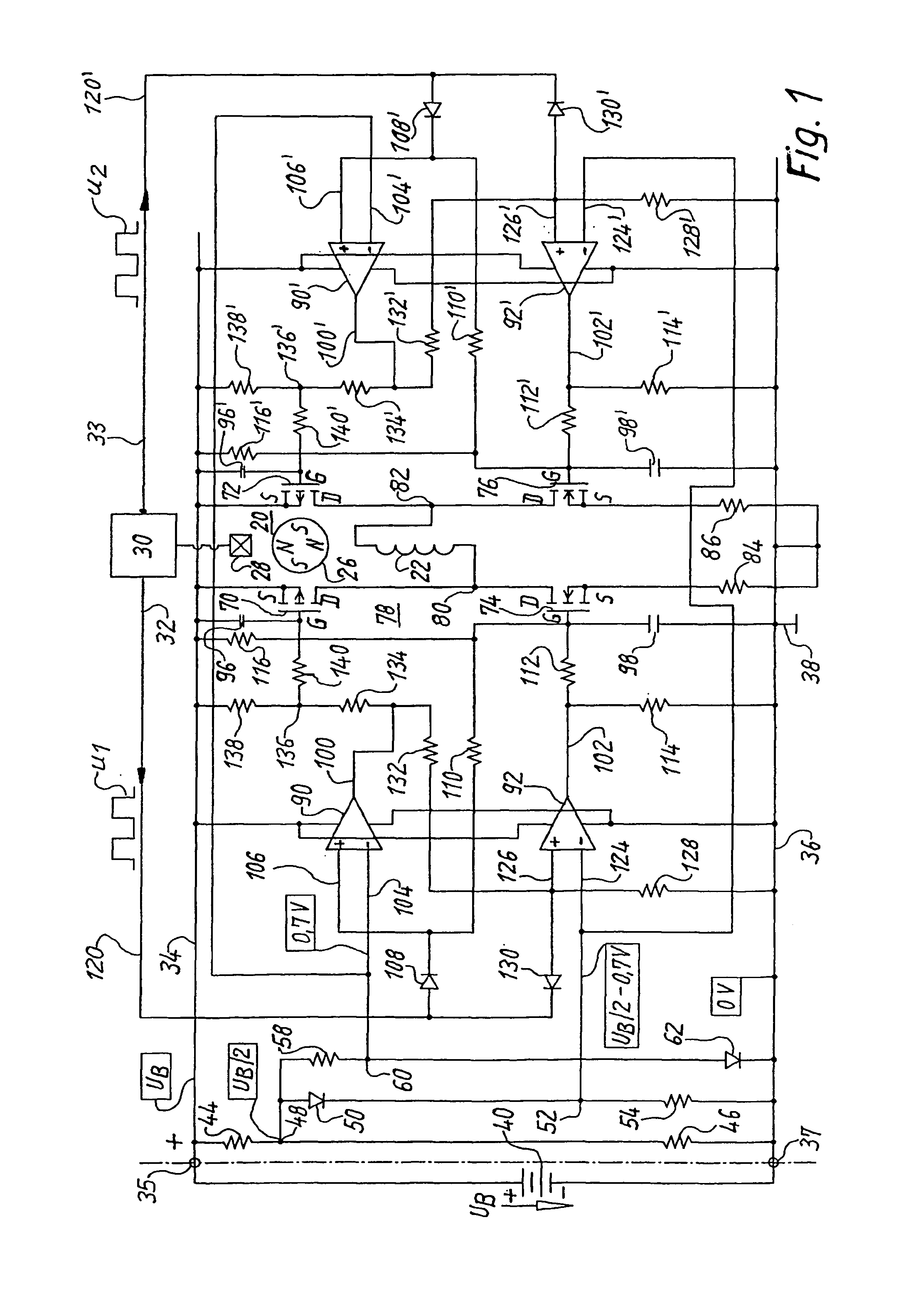
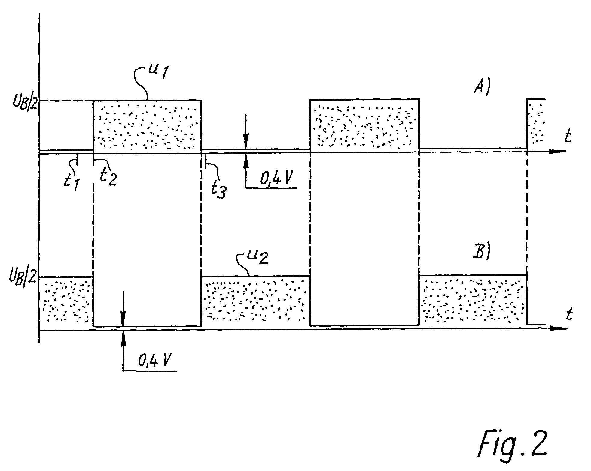
[0013]FIG. 1 shows, for explanation of the invention, a single-phase two-pulse electronically commutated motor 20 having a single stator winding phase 22, also having a permanent-magnet rotor 26 that is depicted as a four-pole rotor, and having a Hall generator 28 whose output signal is fed to an arrangement 30 having an output 32 and an output 33 antivalent thereto. In arrangement 30, the output signal of Hall generator 28 is converted into two square-wave signals u1 and u2, which are depicted in FIG. 2 and proceed in oppositely-phased fashion. These can, if necessary, be shifted in phase in known fashion as a function of the rotation speed of motor 20; this is not depicted.

[0014]Motor 20 is supplied with voltage via a positive connecting lead 34 and a negative connecting lead 36 that is usually connected to ground 38. Leads 34, 36 can be connected via respective connecting terminals 35 and 37 to a battery 40 whose voltage is labeled UB and is usually, in this case, in the range be...


PUM


Abstract

An improved method of commutating an electronically commutated motor (20) is disclosed. The motor has a positive (34) and a negative connecting lead (36), a stator having at least one winding phase (22), a permanent-magnet rotor (26), a rotor-position sensor (28) for producing a rotor position signal (u1, u2), and a full bridge circuit (78), comprising a pair of Metal Oxide Semiconductor Field Effect Transistors (MOSFETs) coupled to each end of each winding phase (22). In order to prevent current shoot-through and prolong the service life of the MOSFETs, without employing a microprocessor, a respective-comparator (90, 90′, 92, 92′) is coupled to the gate of each MOSFET, in order to assure that the MOSFET is switched ON and OFF at an optimum time.

Description

[0001]This application is a § 371 of PCT / EP03 / 00834, filed 28 Jan. 2003.FIELD OF THE INVENTION[0002]The invention concerns a method for commutating an electronically commutated motor, and a motor for carrying out such a method.BACKGROUND[0003]Electronically commutated motors operate with a stator winding that has a small number of phases. The motors principally used have one, two, or three phases. These phases can have power supplied to them in different ways depending on the type of electronics; supplying power via a full bridge circuit offers particular advantages.[0004]With a full bridge circuit, steps must be taken to ensure that a short circuit does not occur in the full bridge. There are numerous circuits for this, for example the circuit according to U.S. Pat. No. 4,376,261, von der Heide, et al., which is based on the principle of creating a small gap between two control pulses. When the full bridge is controlled via a microprocessor (μP), corresponding current off-times can...

Claims


Application Information

Patent Timeline
Patent Type & Authority Patents(United States)
IPC IPC(8): H01R39/46H02P6/15
CPCH02P6/142H02P6/15
Inventor BERROTH, HANSJORG
Owner EBM PAPST ST GEORGEN & -
Why Eureka
Try Eureka