
Socket connector for receiving a plurality of termination sockets for coaxial cables

a technology of coaxial cable and socket connector, which is applied in the direction of coupling device connection, electrical apparatus, coupling protective earth/shielding arrangement, etc., can solve the problems of low miniaturization efficiency, loss of signal transmission, and increase of signal reflection properties of the termination socket, etc., to achieve easy assembly, stable construction, and easy manufacturing

Inactive Publication Date: 2006-03-14
3M INNOVATIVE PROPERTIES CO
View PDF32 Cites 3 Cited by
  • Summary
  • Abstract
  • Description
  • Claims
  • Application Information

AI Technical Summary

Benefits of technology

[0022]It has been found out in electrical measurements that the path length of the ground bussing connections between the shielded cable termination sockets is rather important for the signal transmission at high speeds and frequencies. Therefore, by the invention it is suggested to design the electrical path between adjacent shielded cable termination sockets of the socket connector very short. This is achieved according to the invention by providing electrical interconnection between adjacent shielded cable termination sockets through the wall sections of the socket connector which wall sections are arranged between adjacent termination sockets for the shielded cables. These wall sections have two or more contact surfaces electrically conductive and limiting the adjacent receiving portions or compartments of the housing of the socket connector which compartments or receiving portions receive the individual termination sockets. The opposite contact surfaces of the wall sections contact the housings of the shielded cable termination sockets when inserted in the receiving portions or compartments and are electrically connected to each other. By this design the electrically paths between two adjacent termination sockets are as short as possible. This feature in turn provides for good signal transmission at increased signal speeds and frequencies up to several GHz at merely very few attenuation e.g. of 3 dB. Accordingly, the low inductive and, therefore, the low impedance connection between the termination sockets for the shielded cables ensure a large band width for the signals to be transmitted and thus a reduced reflection phenomena. Accordingly, the socket connector of the present invention provides for an increased frequency band width of signal transmission while simultaneously reducing the attenuation.
[0025]SCI termination sockets can be easily mounted within the receiving portions or compartments of a socket connector. Within the socket connector SCI termination sockets can be arranged at a rather high density due to their box-shaped housing or casing.
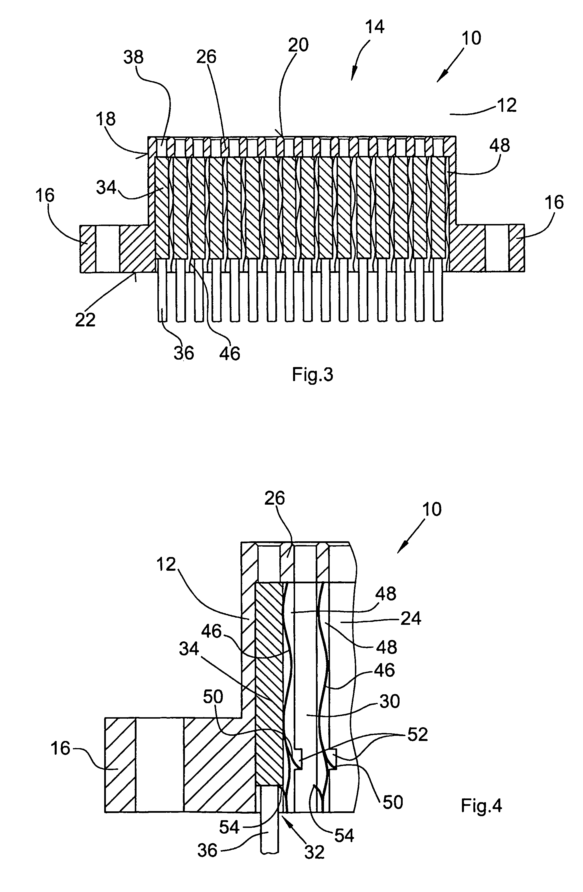
[0032]Moreover, it is preferred to design the wall sections as individual elements separated from the socket housing. These separated elements are inserted into the housing. This design is advantageous in that the housing can be made of a dielectric plastics material which can be easily manufactured by a molding process, in particular an injection molding process, as well as other material can be used, e.g. metal in an injection molding or diecast process. while the separated wall section elements can be manufactured from a metal material in particular a metal material with resilient properties like a sheet of spring steel. Preferably, the separated wall section elements inserted into the socket housing are secured therein against an undesired removal therefrom by means of at least one locking element for each wall section element. These locking elements most preferable are in snap fit engagement with the socket housing or the wall section element. The wall section elements most preferably are inserted in receiving slots of the socket housing confronting each other so that the lateral edges of each wall section element is received by one receiving slot of a pair of receiving slots. In this design the socket housing comprises at least one receiving area formed by a recess in the socket housing and having confronting major wall portions between which the wall section elements are arranged parallel to each other so as to divide the receiving recess in a plurality of adjacent receiving portions. The embodiments of the invention having separated wall section elements inserted and guided into opposite guiding slots for receiving the opposite lateral edges of a respective wall section element are advantageous concerning easy assembly and stable construction of the socket connector with a reliable electrical connection between adjacent coaxial cable termination sockets.

Problems solved by technology

Due to the substantially cylindrical design of these known termination sockets, they are less suitable for miniaturization.
However, the increased requirements for electrical equipment in particular information technology equipment such as in telecommunication multiplexer lead to a high signal density of connections i.e. a high number of cable connections in a limited space.
A certain disadvantage of coaxial cable termination sockets having a box-shaped design i.e. having a design which is non-coaxial, results in a loss of signal transmission and increase of signal reflection properties of the termination socket for high frequent signals in the range of MHz.
While the box-shaped coaxial cable termination sockets basically work fine concerning high density packaging aspects, there are limits concerning the speed and frequency of the signals transmitted through the termination sockets.
This arrangement does not provide positive grounding for each cable particularly with a high number of cables.
However with such an arrangement it is not possible to transmit very high speed and frequency signals.
Moreover, the assembly of the known socket connectors with the gripping ground means is rather time-consuming and cumbersome.
This arrangement comprises many parts and does not meet the requirements of a cost-efficient solution for coaxial cable termination since it is expensive and complex to manufacture or assemble, respectively.

Method used


Image

  • Socket connector for receiving a plurality of termination sockets for coaxial cables
  • Socket connector for receiving a plurality of termination sockets for coaxial cables
  • Socket connector for receiving a plurality of termination sockets for coaxial cables

Examples


Embodiment Construction

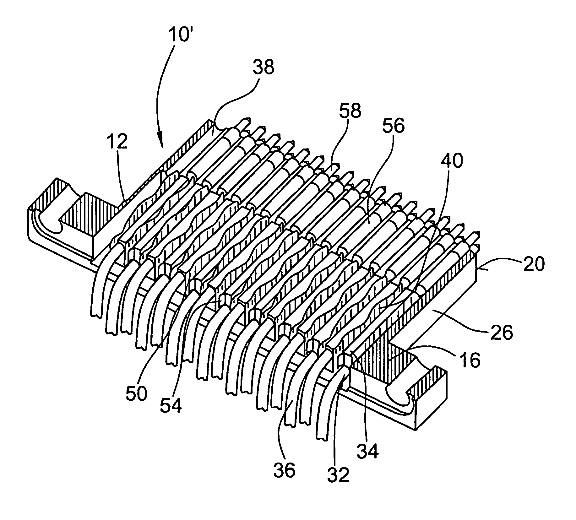
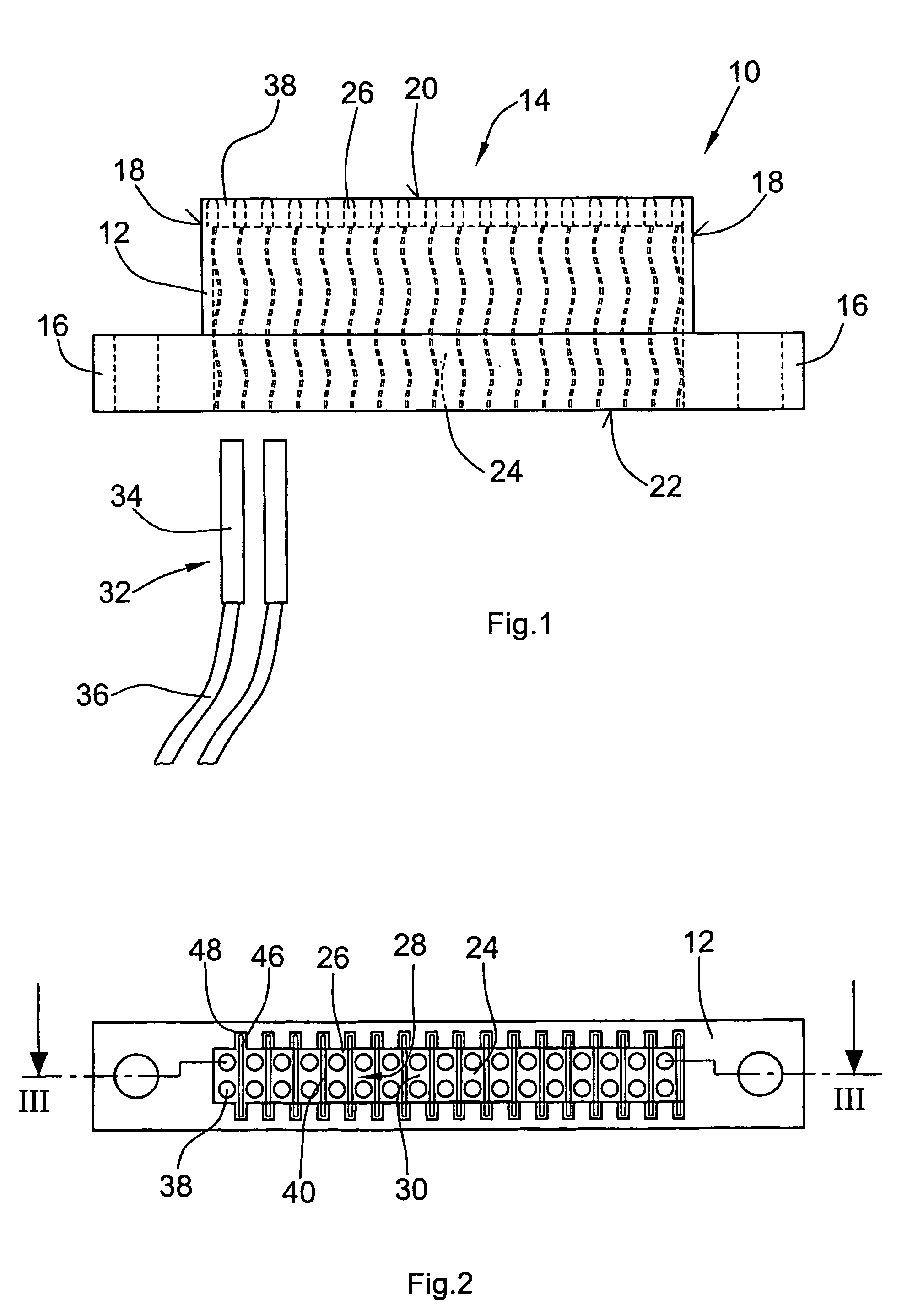
[0047]In FIGS. 1 to 5 a first embodiment of a socket connector 10 is shown. The socket connector 10 comprises a housing 12 of dielectric or electrically conductive material having a major portion 14 and two flange portions 16 extending from opposite lateral sides 18 of the major portion 14. The flange portions 16 are not necessarily required. Beside the lateral sides 18 the major portion 14 of the housing 12 of the socket connector 10 is limited by a front end 20 and a rear end 22.

[0048]As can be seen from FIG. 2 the housing 12 is provided with a recess 24 extending substantially along the complete width of the major portion 14 between the flange portions 16 and along the major portion 14 towards the front end 20. The recess 24 is open at the rear end 22 and is limited by a bottom wall portion 26 of the housing 12. As also depicted in FIG. 2, the recess 24 is divided by individual wall sections 28 into compartments or receiving portions arranged in a row and separated by the wall se...


PUM


Abstract

The socket connector for receiving a plurality of termination sockets for shielded cables each having a signal conductor and a cable shield electrically insulated relatively to the signal conductor, each termination socket having (1) a housing of electrically conductive material, at least one signal contact element within the housing and electrically insulated relatively to the housing and electrically connected to the signal conductor, and (2) at least one ground contact element within the housing and electrically insulated relatively to the signal contact element and electrically connected to the cable shield and the housing, comprises a housing (12) having adjacent receiving portions (30) for receiving the housings (34) of a plurality of shielded cable termination sockets (32), and wall sections (40) arranged between adjacent receiving portions (30), each wall section (40) comprising contact surfaces (42,44) electrically conductive and limiting the adjacent receiving portions (30) and for contacting the housings (34) of the shielded cable termination sockets (32) when inserted in the receiving portions (30), wherein said contact surfaces (42, 44) of each wall section (40) are electrically connected to each other.

Description

[0001]This application is a 371 of PCT / EP02 / 07670 filed on Oct. 7, 2002.BACKGROUND OF THE INVENTION[0002]1. Field of the Invention[0003]The present invention relates to improvements on socket connectors for receiving a plurality of termination sockets for coaxial cables and, in particular, for coaxial cables having a small diameter and allowing high speed and large band width signal transmission.[0004]2. Description of the Prior Art[0005]Basically, for connecting coaxial cables to components of electrical equipment connectors and termination sockets are used which are rotationally symmetrical with respect to their longitudinal axis. The design of these termination sockets provides a resistance behavior which is substantially identical to the behavior of the cable and, moreover, also provides a good shielding effect. Rotationally symmetrical coaxial cable termination sockets are disclosed in U.S. Pat. Nos. 4,943,245, 4,923,412, and DE 37 32 520. Due to the substantially cylindrical d...

Claims


Application Information

Patent Timeline
IPC IPC(8): H01R9/05H01R13/658
CPCH01R13/65807H01R9/05
Inventor BRANDT, KONRAD W.JUENEMANN, MARCUS
Owner 3M INNOVATIVE PROPERTIES CO
Learn More