
Icemaker

a technology of icemaker and ice maker, which is applied in the field of icemaker, can solve problems such as quality ice, and achieve the effect of preventing ice from being cracked or broken

Inactive Publication Date: 2006-03-14
SAMSUNG ELECTRONICS CO LTD
View PDF17 Cites 64 Cited by
  • Summary
  • Abstract
  • Description
  • Claims
  • Application Information

AI Technical Summary

Benefits of technology

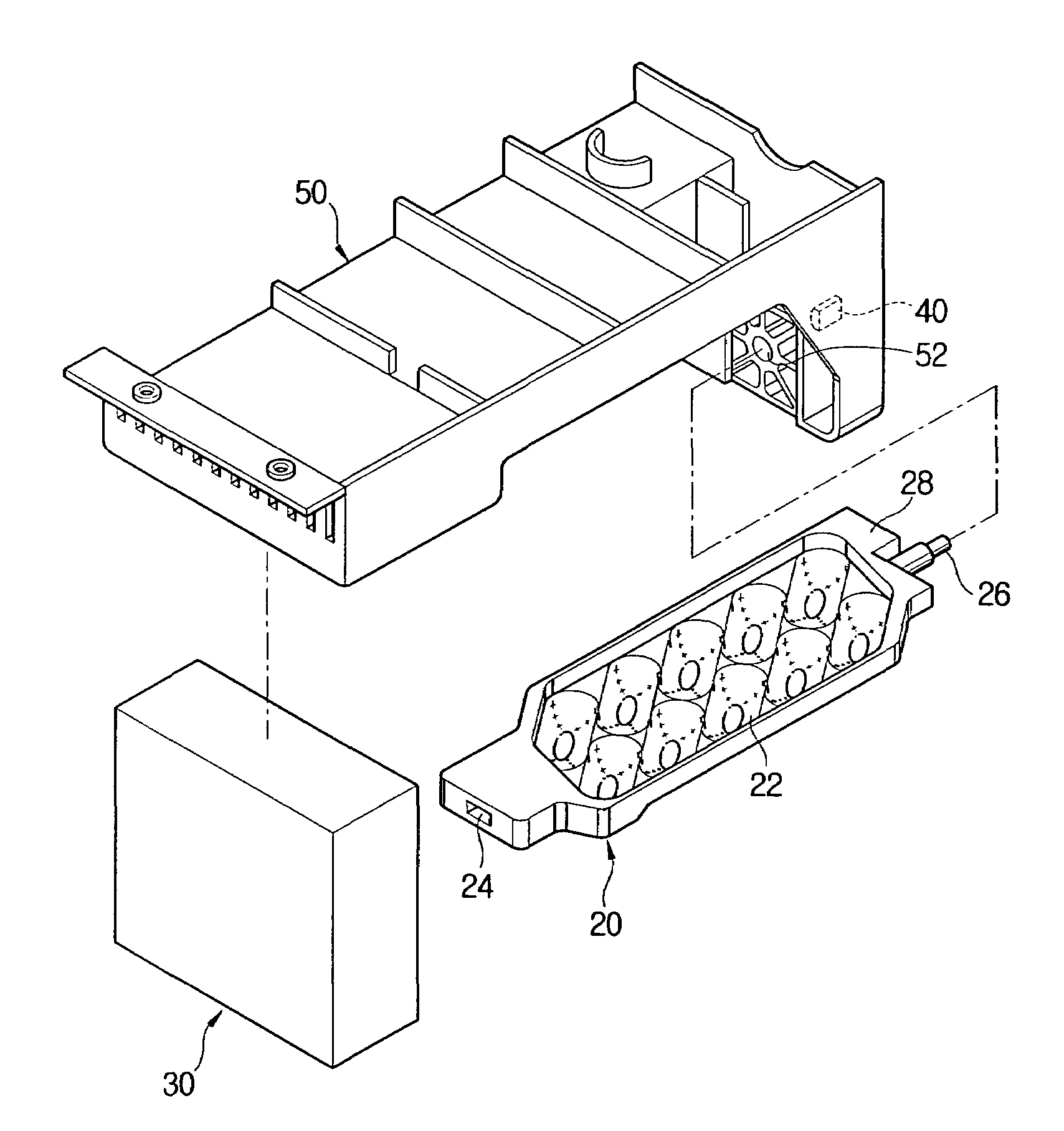
The present invention provides an icemaker that prevents ice from cracking or breaking while releasing it from an ice cube tray. This is achieved by designing the ice cube tray with diagonally arranged cube compartments that are twisted by an actuator and a stopper coming into contact with the tray. The angle of the cube compartments is about 40-50 degrees with respect to the lengthwise direction of the tray, and each compartment has an oblong shape with a crescent shape. The icemaker also includes a supporting bracket supporting the actuator and the ice cube tray, with the stopper provided in one side of the bracket. The ice cube tray is formed with an ice-releasing portion at one side thereof to come into contact with the stopper.

Problems solved by technology

Accordingly, there arises a problem to make quality ice.

Method used


Image

  • Icemaker
  • Icemaker
  • Icemaker

Examples


first embodiment

[0038]With this configuration, the icemaker according to the present invention is operated as follows.

[0039]First, the cube compartments 22 of the ice cube tray 20 is filled with water supplied from a water supplying part, and then the water is frozen into the ice by a cooling means such as cool air for a predetermined period of time.

[0040]Then, the actuator 30 is operated to rotate the ice cube tray 20 and to release the ice from the cube compartments 22. When the ice cube tray 20 is rotated and reaches a predetermined rotational angle, the ice-releasing portion 28 of the ice cube tray 20 comes into contact with the stopper 40 provided in the supporting bracket 50.

[0041]In the state that the ice-releasing portion 28 is supported by the stopper 40, the actuator 30 continuously rotates the ice cube tray 20, so that one portion of the ice cube tray is stopped and the other portion thereof is rotated, thereby twisting the ice cube tray 20. Thus, the cube compartments 22 are compressed ...

second embodiment

[0046]FIG. 8 is a perspective view of an ice cube tray according to the present invention, and FIG. 9 is a plan view of the ice cube tray of FIG. 8.

[0047]As shown therein, an ice cube tray 20 of an icemaker according to the second embodiment of the present invention is the same as the ice cube tray 20 of the first embodiment except the arranged structure of the cube compartments 22. That is, in the second embodiment the cube compartments 22 are arranged at a forward inclination angle with respect to the lengthwise direction of the ice cube tray 20, while in the first embodiment the cube compartments 22 are arranged at a backward inclination angle with respect to the lengthwise direction of the ice cube tray 20.

[0048]According to the second embodiment, the cube compartments 22 are tensioned transversely with respect to the lengthwise direction of the ice cube tray 20 while the ice cube tray 20 is twisted, thereby releasing the ice from the cube compartments 22.

[0049]As described abov...


PUM


Abstract

The present invention relates to an icemaker in which an ice cube tray is twisted by rotation of an actuator to easily and effectively release ice from the ice cube tray.The icemaker comprising an ice cube tray formed with cube compartments; an actuator rotating the ice cube tray; and a stopper coming into contact with the ice cube tray being rotated and allowing the ice cube tray to be twisted, the cube compartments being diagonally arranged with respect to a lengthwise direction of the ice cube tray. With this configuration, the present invention provides an icemaker in which an ice is easily released from an ice cube tray and minimally cracked or broken while being released.

Description

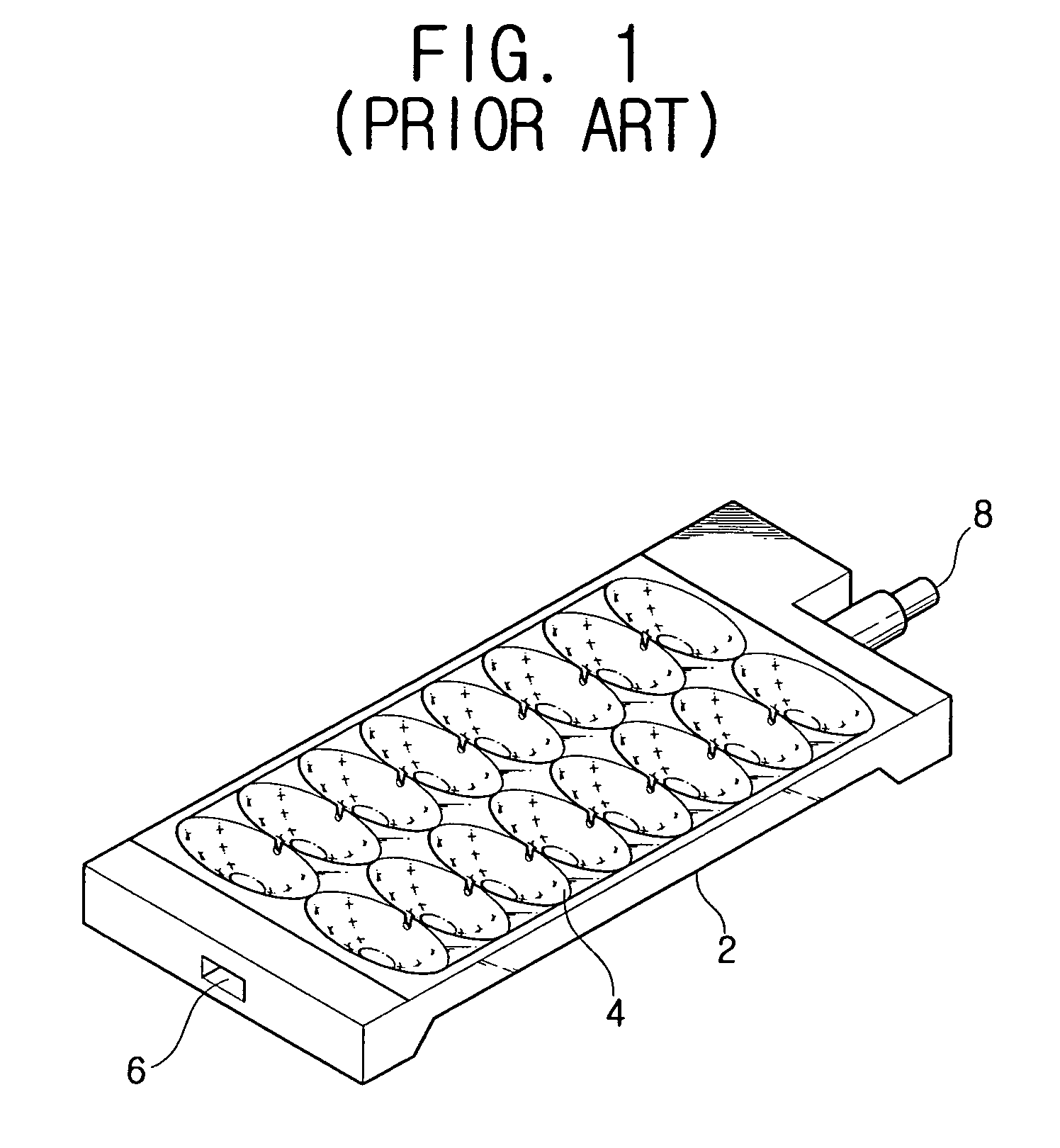
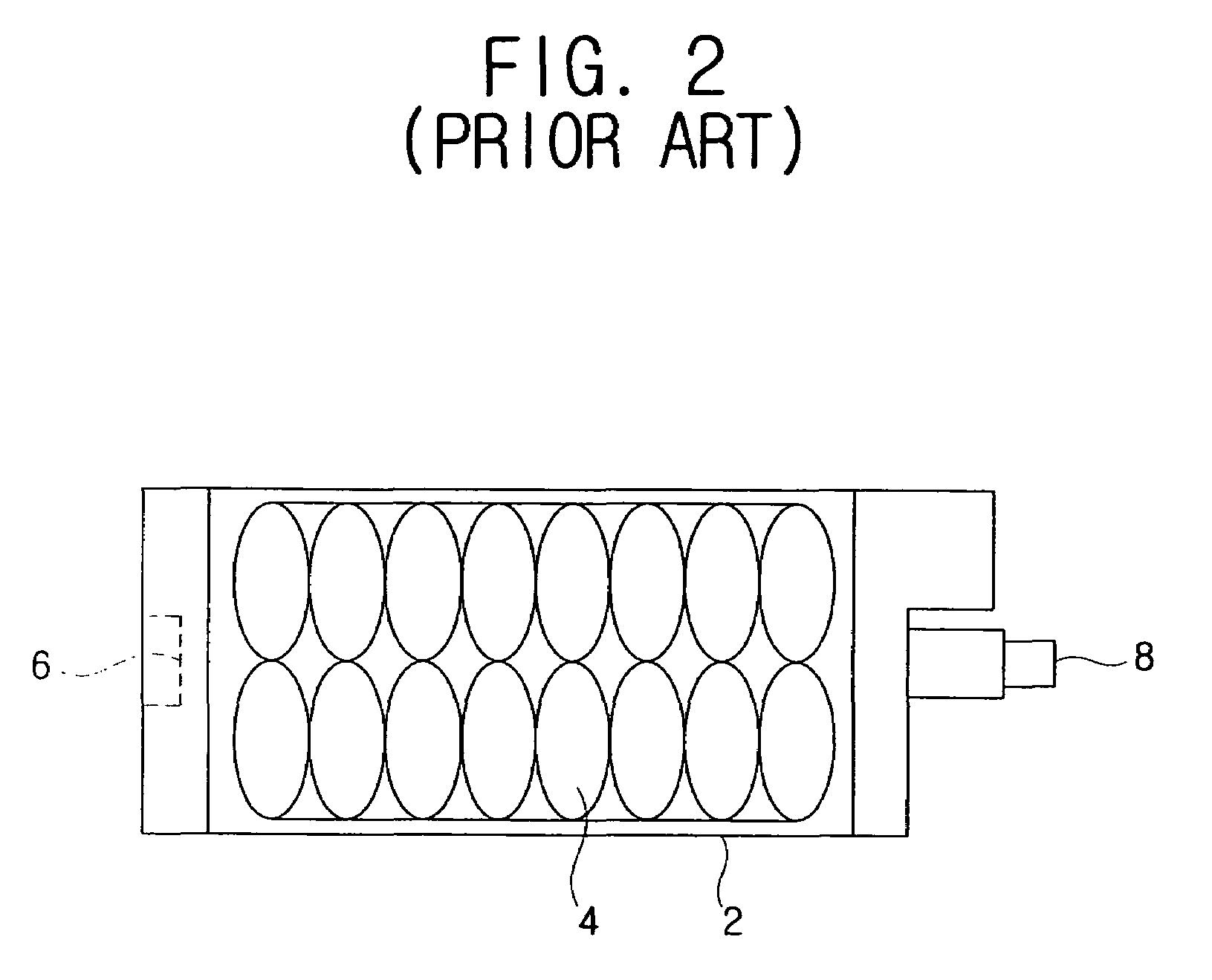
CROSS-REFERENCE TO RELATED APPLICATIONS[0001]This application claims the benefit of Korean Patent Application No. 2004-5428, filed Jan. 28, 2004, in the Korean Intellectual Property Office, the disclosure of which is incorporated herein by reference.BACKGROUND OF THE INVENTION[0002]1. Field of the Invention[0003]The present invention relates to an icemaker, and more particularly, to an icemaker in which an ice cube tray is twisted by rotation of an actuator to easily and effectively release ice from the ice cube tray.[0004]2. Description of the Related Art[0005]Generally, an icemaker for freezing water into ice is being widely applied to home appliances such as a refrigerator, a water purifier, etc.[0006]Most of conventional icemaker comprises an ice cube tray formed with a plurality of cube compartments; a motor coupled to the ice cube tray and rotating the ice cube tray; and a stopper coming into contact with the ice cube tray rotated by the motor and allowing the ice cube tray to...

Claims


Application Information

Patent Timeline
Patent Type & Authority Patents(United States)
IPC IPC(8): F25C1/04F25C1/22F25C1/10F25C1/24
CPCF25C1/10F25C1/24F25C1/22
Inventor CHOI, SANG-KEUNCHANG, EUI-YOUNG
Owner SAMSUNG ELECTRONICS CO LTD
Learn More