Ultrasonically cleaned membrane filtration system

Inactive Publication Date: 2006-03-07
THE OHIO STATES UNIV
View PDF14 Cites 167 Cited by
  • Summary
  • Abstract
  • Description
  • Claims
  • Application Information

AI Technical Summary

Benefits of technology

[0011]The present invention utilizes ultrasound to improve the performance of cross-flow membrane filtration for liquid / particle or liquid / colloid separation. The filtration system minimizes membrane fouling and / or maintains non-fouling conditions during membrane filtration processes leading to increased permeation. The ultrasonic transducer may be operated either continuously or periodically to maintain a level of permeation.
[0012]In one embodiment, the filtration system includes an electronic controller and transducers, which transform electrical energy into mechanical vibrations. The ultrasonic energy propagates toward the membrane surface through a liquid medium. Once this high-powered ultrasound is introduced into liquid solution, cavitation bubbles are formed during the rarefaction of sound waves. When the cavitation bubbles collapse, localized hot spots are formed which reach high temperatures and pressures. Associated with cavitation bubbles and ultrasonic energy, micro-streaming, micro-streamers, micro-jets, shock waves, and acoustic streaming are generated, that are capable of removing particles and the fouling layer from the membrane surface. In addition, these physical effects produced from ultrasound can both reduce concentration polarization and prevent the deposition of particles that lead to fouling.
[0015]Ultrasound has significant advantages over traditional methods that control membrane fouling. For example, there are no chemicals used in the membrane cleaning process, and filtration is not interrupted to perform cleaning. In addition, this technique is useful for both large- and small-scale systems, and would require little maintenance. The maintenance of overall higher permeate fluxes reduces trans-membrane pressures and total membrane area requirements.

Problems solved by technology

This method involves disadvantages, because it necessitates the demounting of a part of the system and because it involves the handling of a large volume of waste materials, comprising all the impurities retained by the cleaned filtering elements and these filtering elements themselves.
This leads to increased labor cost and an increased period of non-availability of the filtration system; furthermore, it may be necessary to handle and to process large quantities of waste materials after cleaning of the filter.
Additional difficulties arise when the filtration systems of the type described hereinabove are utilized for the processing of fluids containing impurities consisting of dangerous materials.
Requiring the replacement of such filtering elements increases the risk of exposing maintenance personal to such contaminates.
However, backwashing is not ideal in that the volume of fluid necessary to carry out the cleaning may be fairly large causing possible filtration membrane degradation, and / or may necessitate the utilization of costly processing stations for the resulting highly contaminated effluent.
Accordingly, in addition to having to isolate the filtration system from the filtration circuit, membrane degradation may be problematic due to the use of inappropriate chemicals.
Further disadvantages include chemical costs, waste handling and disposal costs, and the need for additional operator safety and training to use this type of regeneration process.
However, using ultrasound has not been without its disadvantages.
For example, prior art methods have used a membrane housing or other barrier between the ultrasonic energy and the membrane surface, thereby requiring additional power input.
Additionally, because such systems have an intermediate medium through which to transmit ultrasonic energy, such prior systems have also be unable to provide a uniform distribution of the ultrasonic energy to the fouled membrane surface.

Method used


Image

  • Ultrasonically cleaned membrane filtration system
  • Ultrasonically cleaned membrane filtration system
  • Ultrasonically cleaned membrane filtration system

Examples


Embodiment Construction

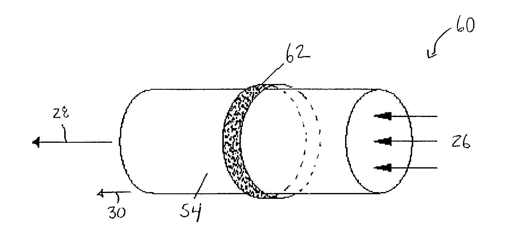
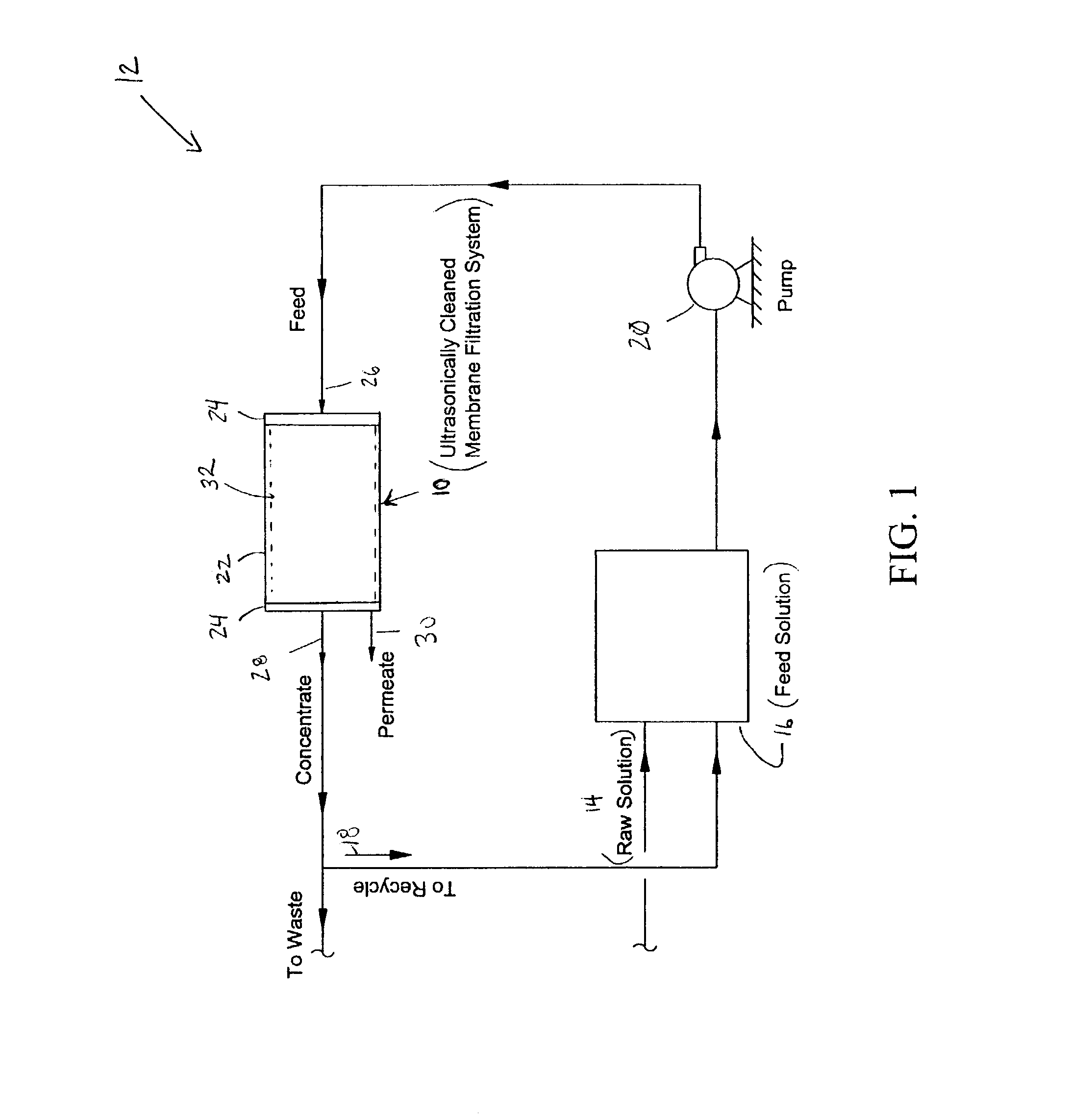
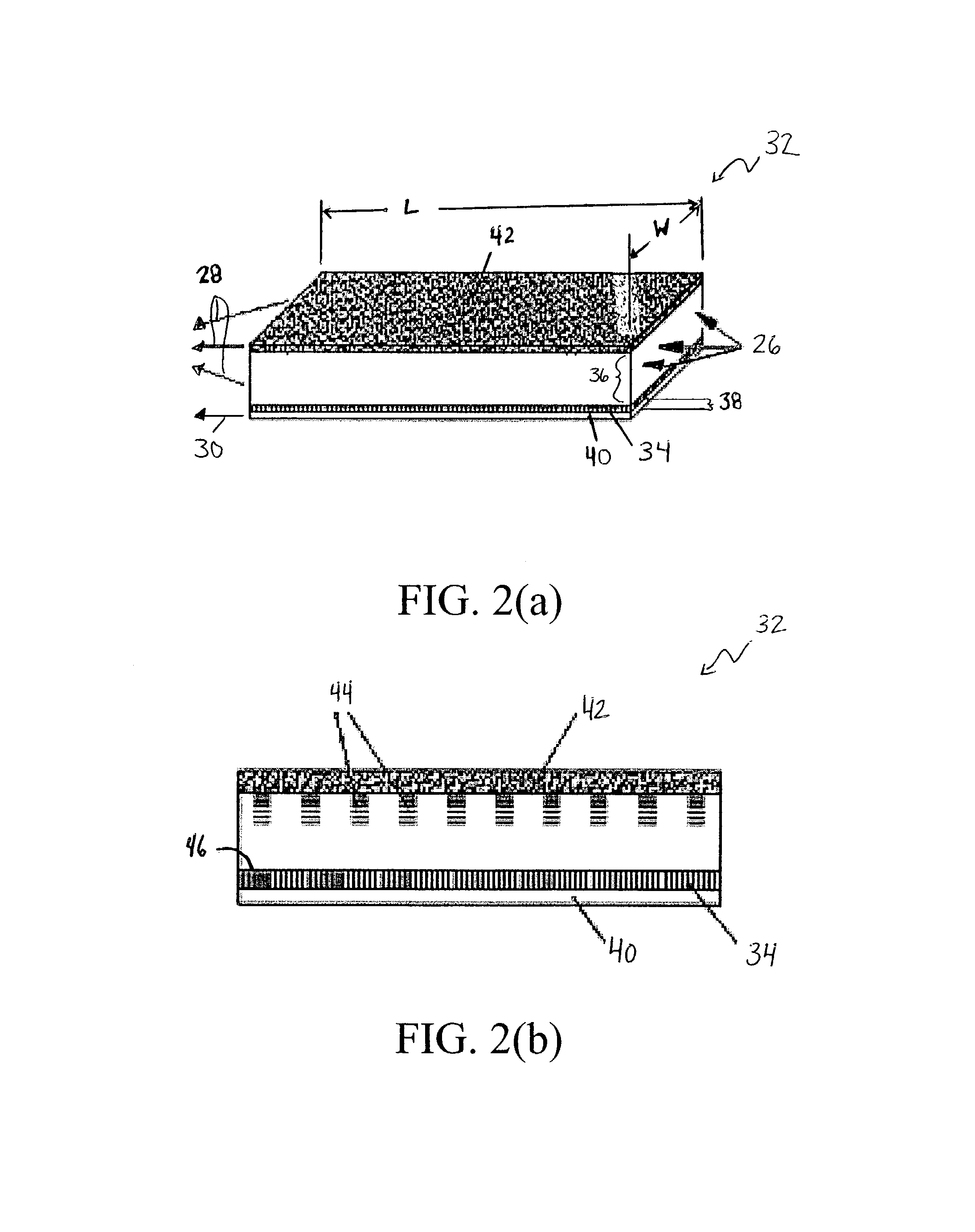
[0030]FIG. 1 is a schematic block diagram of an ultrasonically cleaned membrane filtration system 10 incorporated into a filtration circuit 12 according to an embodiment of the present invention. The filtration system includes one or multiple ultrasonic transducer systems located adjacent to a filtration membrane in direct contact with a liquid to be filtered. Examples of different types of filtration membranes suitable for use with the present invention include, but not limited to, flat sheet, tubular, spiral wound and hollow fiber filtration membranes.

[0031]The filtration circuit 12 includes a raw solution source 14 connected to a feed solution source 16. In one embodiment, the raw solution and feed solution may be one in the same. In another embodiment, a recycle source 18 of concentrate exiting the membrane filtration system 10 and the raw solution source 14 may be combined to provide the feed solution source 16. A pump 20 pumps the feed solution source 16 to provide the liquid ...


PUM

PropertyMeasurementUnit
Metallic bondaaaaaaaaaa
Frequencyaaaaaaaaaa
Energyaaaaaaaaaa

Abstract

A filtration system and a method of cleaning a particle and / or colloidal fouled filtration membrane are provided. The filtration system includes at least one filtration membrane disposed in a casing, and at least one ultrasonic transducer in direct contact with a fluid to be filtered. Ultrasonic energy is emitted by the ultrasonic transducer in the direction of the filtration membrane. Dislodged particles cleaned by the ultrasonic energy from the filtration membrane are carried away in a cross-flow stream and wasted or recycled back to the beginning of the treatment process. The ultrasonic transducer can be fixed or movable. The filtration system can use different filtration membrane configurations such as, but not limited to, tubular, flat sheet, hollow fiber and spiral wound membranes.

Description

[0001]This application is a continuation of U.S. patent application Ser. No. 10 / 408,763, filed Apr. 7, 2003, now abandoned.BACKGROUND OF THE INVENTION[0002]The invention relates to a filtration system comprising a device for the ultrasonic cleaning of its filtering elements and a corresponding cleaning process.[0003]Systems are known which are used for the filtration of liquids and which comprise, within a casing, a set of filtering elements made of porous material(s) or membranes. The use of membranes is a widely employed, versatile, and effective separation process. Different membrane types, ranging from micro-filtration (MF) to reverse osmosis (RO), are capable of removing suspended particles and microorganisms to rejecting virtually all ions in solution, respectively.[0004]During the operation of the filtration system, impurities from the fluid progressively fill the interstices of the porous material and / or form a cake layer on top of the porous material. In order to maintain s...

Claims


Application Information

Patent Timeline
IPC IPC(8): B01D65/02
CPCB01D63/02B01D63/06B01D63/08B01D65/08B01D65/02B01D2313/34B01D2321/2075B01D63/031
Inventor WEAVERS, LINDA KAYWALKER, HAROLD W.LAMMINEN, MIKKO O.CHEN, DONG
Owner THE OHIO STATES UNIV
Why Eureka
Try Eureka