
Portable power working machine

a working machine and power technology, applied in the field of portable power working machines, can solve the problems of deteriorating the working efficiency of the working machine, accelerating the speed of the clogging of the filter, and unavoidable dust accumulation, so as to improve the system's working efficiency

Active Publication Date: 2006-03-07
KIORITZ
View PDF2 Cites 14 Cited by
  • Summary
  • Abstract
  • Description
  • Claims
  • Application Information

AI Technical Summary

Benefits of technology

"The present invention provides a portable power working machine that minimizes clogging of the air cleaner, reducing the need for frequent maintenance. This is achieved by designing an air cleaner with a base body case and a cleaner cover that guides outside air towards the filter, allowing dust to be sucked out through a negative pressure generated by a fan. The air cleaner also includes a suction port and a suction guiding member to discharge dust out of the air cleaner. The machine further includes a negative pressure-generating region where part of the air sucked into the air cleaner passes without passing through the filter, allowing the dust to be peeled away and discharged into the external atmosphere. This results in an effective removal of dust and a reduction in clogging of the filter, improving system efficiency and extending the maintenance cycle of the air cleaner."

Problems solved by technology

In view of the structure of the air cleaner however, the clogging of the filter due to dust would be unavoidably caused to occur, so that the maintenance (the cleaning of the filter or the exchange of the filter with a new one) of the air cleaner is required to be performed periodically, the frequency thereof being dependent on the environment of use and the operating time of the engine.
As explained above, the conventional portable power working machine such as a brush cutter is accompanied with problems that, since dust including chips of branches or leaves of relatively large size, sand-like dust, etc. is permitted to be blown up in the operation of the portable power working machine, the outside air to be sucked into the air cleaner is permitted to intermingle with a large quantity of such dust, thereby accelerating the speed of the clogging of the filter.
As a result, the cycle interval of the maintenance of the air cleaner is shortened and hence correspondingly deteriorates the working efficiency of the working machine.

Method used


Image

  • Portable power working machine
  • Portable power working machine
  • Portable power working machine

Examples


Embodiment Construction

[0021]One embodiment of the present invention will be explained in detail with reference to the drawings as follows.

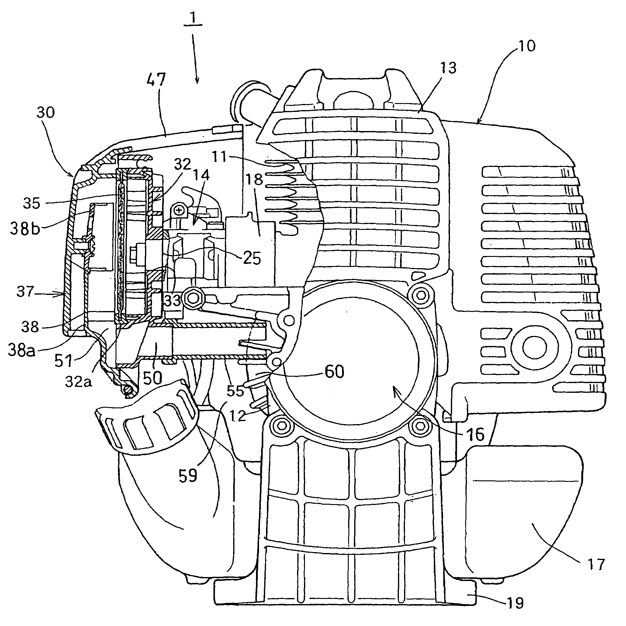
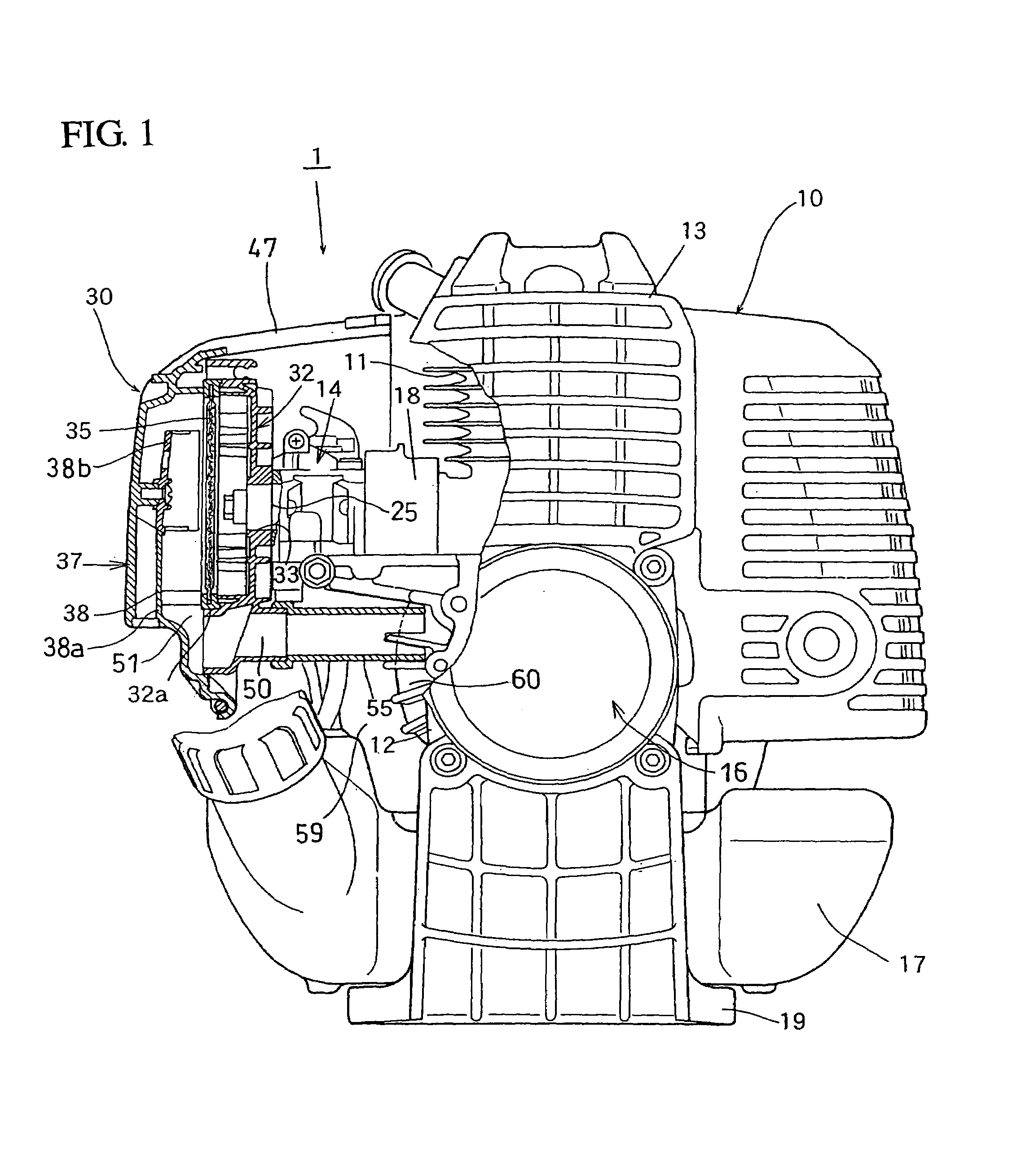
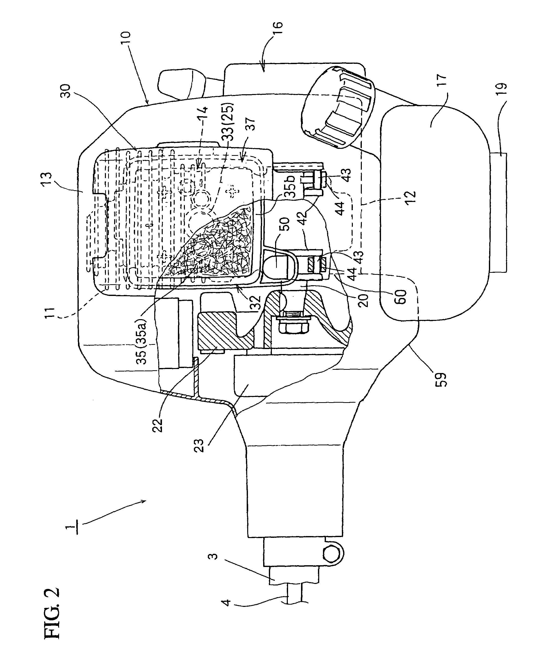
[0022]FIGS. 1 and 2 illustrate a main portion of one embodiment of a brush cutter representing one example of the portable power working machine according to the present invention. The brush cutter 1 according to this embodiment is constructed of substantially the same structure as the brush cutter 2 shown in FIG. 5 except the structure around the air cleaner 30. Therefore, the components which correspond to those of the brush cutter 2 shown in FIG. 5 will be identified by the same reference numbers, thereby omitting duplicated explanation thereof, and hence only the main portions shown in FIGS. 1 and 2 will be explained in the following description.

[0023]The brush cutter 1 shown therein is provided, at a rear end portion of an operating rod 3, with an internal combustion engine (a small, air-cooled, two-stroke cycle gasoline engine) 10 employed as a power source for d...


PUM

PropertyMeasurementUnit
pressureaaaaaaaaaa
frequencyaaaaaaaaaa
sizeaaaaaaaaaa

Abstract

A portable power working machine is disclosed, which is capable of effectively minimizing the clogging of the air cleaner, thereby dispensing with frequent maintenance. This portable power working machine comprises an air cleaner (30) having a base body case (32) provided with a clean air discharge port (33) for introducing the air cleaned into an intake port (25) of a carburetor (14), a filter (35) which is mounted on a filter mounting opening (32a) of base body case (32) so as to seal it, and a cleaner cover (37) which is attached onto the filter (35) so as to cover the filter (35) and to guide outside air toward the filter (35), while giving a predetermined directionality to the outside air. The air cleaner (30) is also configured to include a suction port (50) and a suction guiding member (55) both designed to discharge the dust out of the air cleaner (30) through a space formed between the filter (35) and the cleaner cover (37) as the dust adhered to the outside air side of the filter (35) is sucked out by taking advantage of a negative pressure to be generated by a fan (22).

Description

BACKGROUND OF THE INVENTION[0001]The present invention relates to a portable power working machine such as a brush cutter, a hedge trimmer, etc., which is provided with an internal combustion engine as a driving power source for driving the working components thereof, and in particular, to a portable power working machine which is designed to prevent, as much as possible, an air cleaner attached to an air intake system of an internal combustion engine from being clogged with dust.[0002]One example of the brush cutter representing one embodiment of this kind of portable power working machine is shown in FIG. 5. The brush cutter 2 shown in FIG. 5 is provided, at the distal end portion of the operating rod 3, with a working portion (cutting blade actuating mechanism) 5 comprising a cutting blade 6, a gear case 7, a safety cover 8, etc. The brush cutter 2 is also provided, at the rear end portion of the operating rod 3, with an internal combustion engine (a small air-cooled internal com...

Claims


Application Information

Patent Timeline
Patent Type & Authority Patents(United States)
IPC IPC(8): F02B77/00A01D34/68B01D46/00B01D46/10B01D46/24F02B67/00F02M35/024F02M35/10F02M35/16
CPCB01D46/0004B01D46/0005B01D46/0043B01D46/10B01D2273/30B01D2265/028B01D2271/02
Inventor TAOMO, TOSHIOARAHATA, KOUJIITOH, TOMOKI
Owner KIORITZ
Learn More