Impact driver and fastener removal device

a technology of impact driver and fastener, which is applied in the direction of hand chisels, portable percussive tools, wrenches, etc., can solve the problem that projections cannot be driven sufficiently deep into the fastener head without damaging the device, and achieve the effect of increasing the grasping force of the fastener engagement member and increasing the rotary for

Active Publication Date: 2006-03-07
EAZYPOWER CORP
View PDF10 Cites 7 Cited by
  • Summary
  • Abstract
  • Description
  • Claims
  • Application Information

AI Technical Summary

Benefits of technology

[0009]Another object of the present invention is to provide a device capable of receiving a hammer strike thereupon. A feature of the device is a positioning member that is axially aligned with and removably inserted into the fastener engagement member via a protuberance extending from the positioning member and snugly inserting into a recess in the fastener engagement member. An advantage of the device is that the positioning member “protects” the fastener engagement member from being deformed or otherwise damaged by hammer strikes. Another advantage of the device is that the positioning member transfers the driving force of the hammer to the fastener engagement member thereby forcing the projections of the fastener engagement member to be driven into the fastener head. Still another advantage of the device is that the positioning member is removable from the fastener engagement member to allow a hand tool to be inserted into the recess in the fastener engagement member and impart rotary motion thereupon to ultimately rotate the fastener head to insert the fastener into or extract the fastener from a workpiece.
[0015]Another object of the present invention is to provide an alternative fastener impact driver device capable of receiving a hammer strike without damaging the first and second fastener engagement members. A feature of the device is a positioning member that is axially aligned with and removably inserted into the second fastener engagement member via a protuberance extending from the bottom wall of the positioning member and snugly inserting into a recess in the top wall of the second fastener engagement member. An advantage of the device is the positioning member is readily removed from the top wall of the second fastener engagement member to allow a hand tool to be inserted in the recess in the top wall thereby providing rotary motion to the first and second fastener engagement members to ultimately rotate the fastener head to insert the fastener into or extract the fastener from a workpiece.

Problems solved by technology

However, few of the prior art fastener extraction devices are designed to receive a strike from an impact tool such as a hammer to force “biting” edges or projections of the extraction device into the head of the fastener to allow the extraction device to “grasp” the fastener head and forcibly rotate the head in a predetermined direction with a rotary drive tool.
Further, the prior art impact designs include projections that are limited in number, that engage the fastener head at less than optimum portions and that are designed to “assist” a primary rotational driver (the blade of a screwdriver) to rotate the fastener.
A problem with the prior art impact extraction designs is that the edges or projections are to few in number or are imbedded sufficiently deep into the fastener head and ultimately “break free” from the fastener head before sufficient rotational force is generated to extract the fastener from the workpiece.
Another problem with the prior art designs is that the projections cannot be driven sufficiently deep into the fastener head without damaging the device with a forceful hammer strike.
Yet another problem with the prior art designs is that a deformed or damaged fastener head may include portions that cannot be engaged by corresponding projections from the extraction device resulting to few projections engaging the fastener head to provide sufficient rotational force to remove or insert the fastener from or into the workpiece.

Method used


Image

  • Impact driver and fastener removal device
  • Impact driver and fastener removal device
  • Impact driver and fastener removal device

Examples


Embodiment Construction

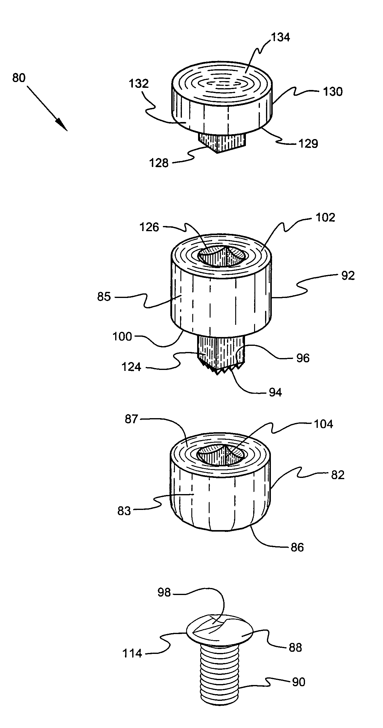
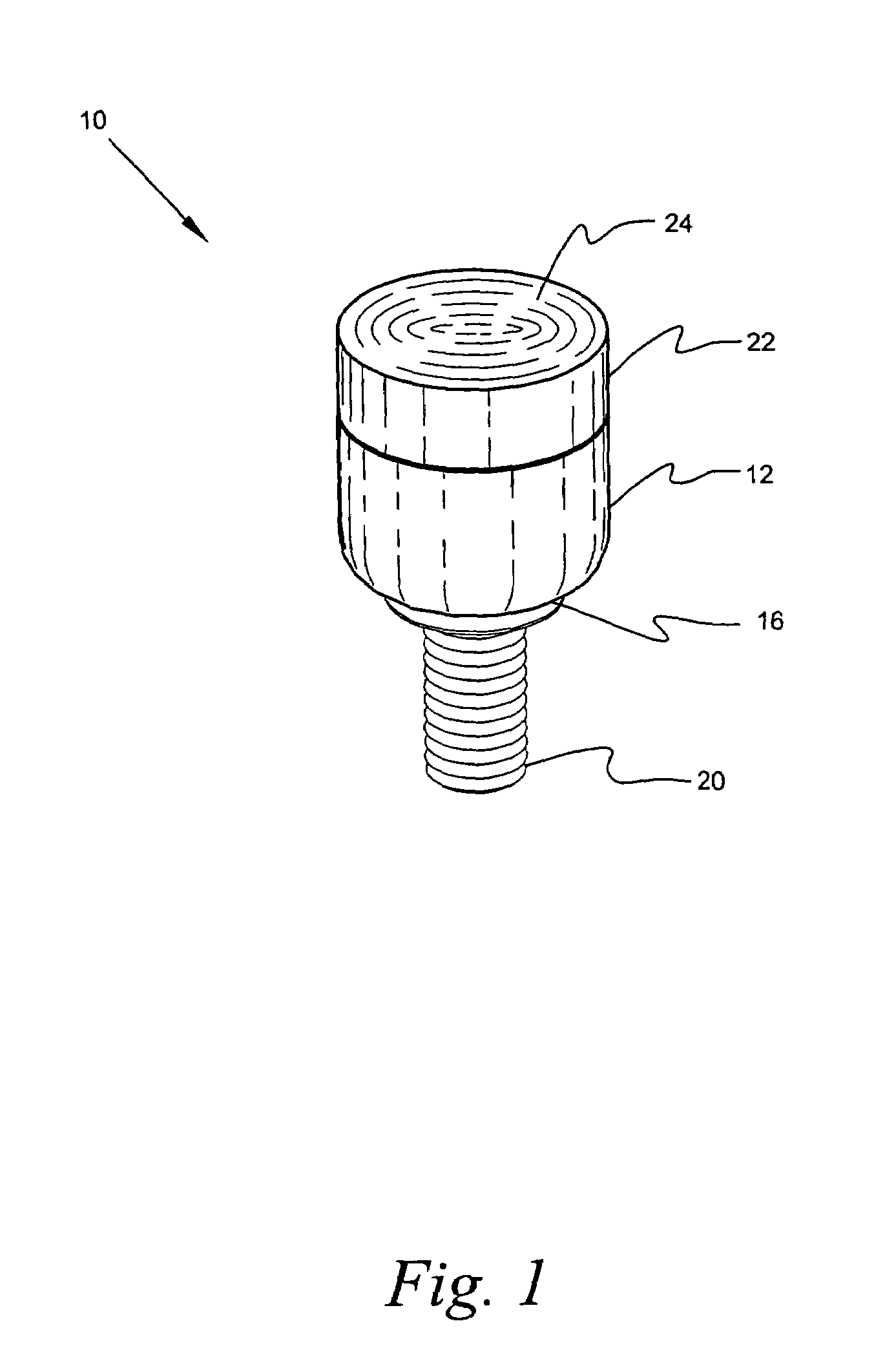
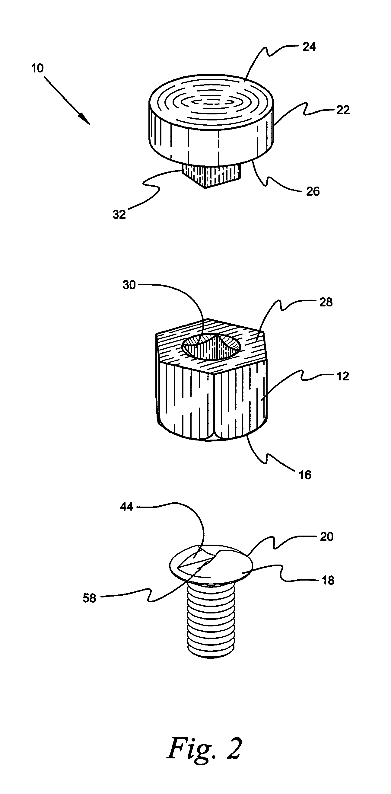
[0056]Referring now to the drawings and in particular to FIGS. 1–9, a fastener impact driver device 10 in accordance with the present invention, is denoted by numeral 10. The device 10 includes a fastener engagement member 12 having a plurality of projections 14 disposed about a lower portion 16 that engages a corresponding peripheral portion 18 of a fastener 20. The device has many applications, but the preferred use is for extracting a one way fastener which is the fastener 20 depicted in FIG. 1. The device 10 further includes a positioning member 22 having an upper portion 24 that ultimately receives a force thereupon, said positioning member 22 having a lower portion 26 that engages a cooperating upper portion 28 of the fastener engagement member 12 whereby a force (a hammer strike) is imparted upon the upper portion 24 of the positioning member 22 to drive the projections 14 of the fastener engagement member 12 into the fastener 20 without damage to the fastener engagement memb...


PUM


Abstract

A fastener impact driver device 10 includes a fastener engagement member 12 having a plurality of projections 14 disposed about a lower portion 16 that engages a corresponding peripheral portion 18 of a fastener 20. The device 10 further includes a positioning member 22 having an upper portion 24 that ultimately receives a force thereupon, and a lower portion 26 that engages a cooperating upper portion 28 of the fastener engagement member 12 whereby a force such a hammer strike is imparted upon the upper portion 24 of the positioning member 22 to drive the projections 14 of the fastener engagement member 12 into the head 44 of the fastener 20 without damage of the fastener engagement member 12, whereupon the positioning member 22 is removed from the fastener engagement member 12 and a hand tool is removably secured to the fastener engagement member 12 to impart rotary motion to the member 12 and the fastener 20 thereby removing the fastener 20 from or urging the fastener 20 into a workpiece.

Description

BACKGROUND OF THE INVENTION[0001]1. Field of the Invention[0002]The present invention relates generally to fastener extraction devices and, more particularly, to fastener impact devices for extracting a fastener from or inserting a fastener into a workpiece by striking the device with a hammer to force grasping projections into the head of the fastener, then removably securing a hand tool to the device to impart rotary motion to the device thereby rotating the fastener in a predetermined direction.[0003]2. Background of the Invention[0004]Fastener extraction devices are well known and are generally designed to remove broken stud bolts and to extract one-way fasteners by the device with a rotary drive tool such as a ratchet. However, few of the prior art fastener extraction devices are designed to receive a strike from an impact tool such as a hammer to force “biting” edges or projections of the extraction device into the head of the fastener to allow the extraction device to “grasp”...

Claims


Application Information

Patent Timeline
Patent Type & Authority Patents(United States)
IPC IPC(8): B25B13/50B25B23/08B25B23/10B25B3/00B25D3/00B25B27/00B25BB25B13/06B25B13/48B25B19/00B25B21/02B25B27/18B25B29/00B25B31/00B25C11/00B25D1/04B25D17/02
CPCB25B13/065B25B27/18B25B13/485B25B19/00B25B27/04
Inventor KOZAK, IRA M.KOZAK, BURTON
Owner EAZYPOWER CORP
Why Eureka
Try Eureka