Electrical connector with one-piece terminals

a technology of electrical connectors and terminals, applied in the direction of coupling contact members, coupling device connections, electrical apparatus, etc., can solve the problems of complex structure and fabrication of terminal assemblies with multiple components, inability to extend or retract, jammed contacting terminals, etc., and achieve excellent resilience and stable extension and retracting functions.

Active Publication Date: 2017-06-06
ADVANCED CONNECTEK INC
View PDF16 Cites 0 Cited by
  • Summary
  • Abstract
  • Description
  • Claims
  • Application Information

AI Technical Summary

Benefits of technology

[0008]The main objective of the invention is to provide an electrical connector that has multiple one-piece terminals. Each one-piece terminal has excellent resilience to provide stable extension and retraction functions. Furthermore, the one-piece terminal is capable of linearly extending or retracting instead of extending or retracting along a non-linearly and irregularly path, which prevents the one-piece terminal from being deformed or damaged.
[0009]An electrical connector in accordance with the present invention comprises an insulative body and multiple terminals. The insulative body has multiple mounting holes and multiple guiding channels. The terminals are mounted respectively the mounting holes and each terminal has an electrically contacting portion mounted slidingly in one of the guiding channels. The guiding channels guides and ensures a corresponding electrically contacting portion to move linearly without being inadvertently jammed or irrecoverably deformed. Therefore, the life-span of the electrical connector is increased.

Problems solved by technology

However, the terminal assembly with multiple components is complicated in structure and fabrication.
Inadvertent dislocation between adjacent components easily occurs and causes the contacting terminal to be jammed and not able to extend or retract.
Furthermore, when large current are transmitted through the terminal assemblies, the terminal assemblies are overheated and the battery connector fails due to an insufficient contacting area between adjacent two of the soldering terminal, the spring and the contacting terminal.
The deformed or jammed contacting portion 93 of the terminal 90 cannot stably contact the pad contact of the battery and therefore causes the defects or failure of power or signal transmission between the battery and the electronic device in which the connector is incorporated.
Furthermore, the connecting section 921 is a straight section being parallel to an axial direction of the terminal 90 and cannot be compressed, which disadvantages the compressing performance of the terminal 90.

Method used


Image

  • Electrical connector with one-piece terminals
  • Electrical connector with one-piece terminals
  • Electrical connector with one-piece terminals

Examples


Embodiment Construction

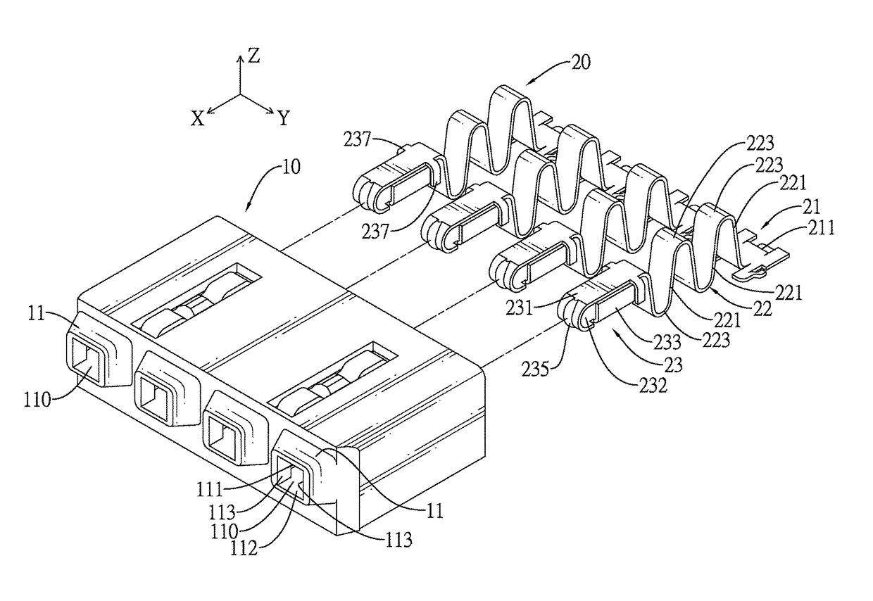
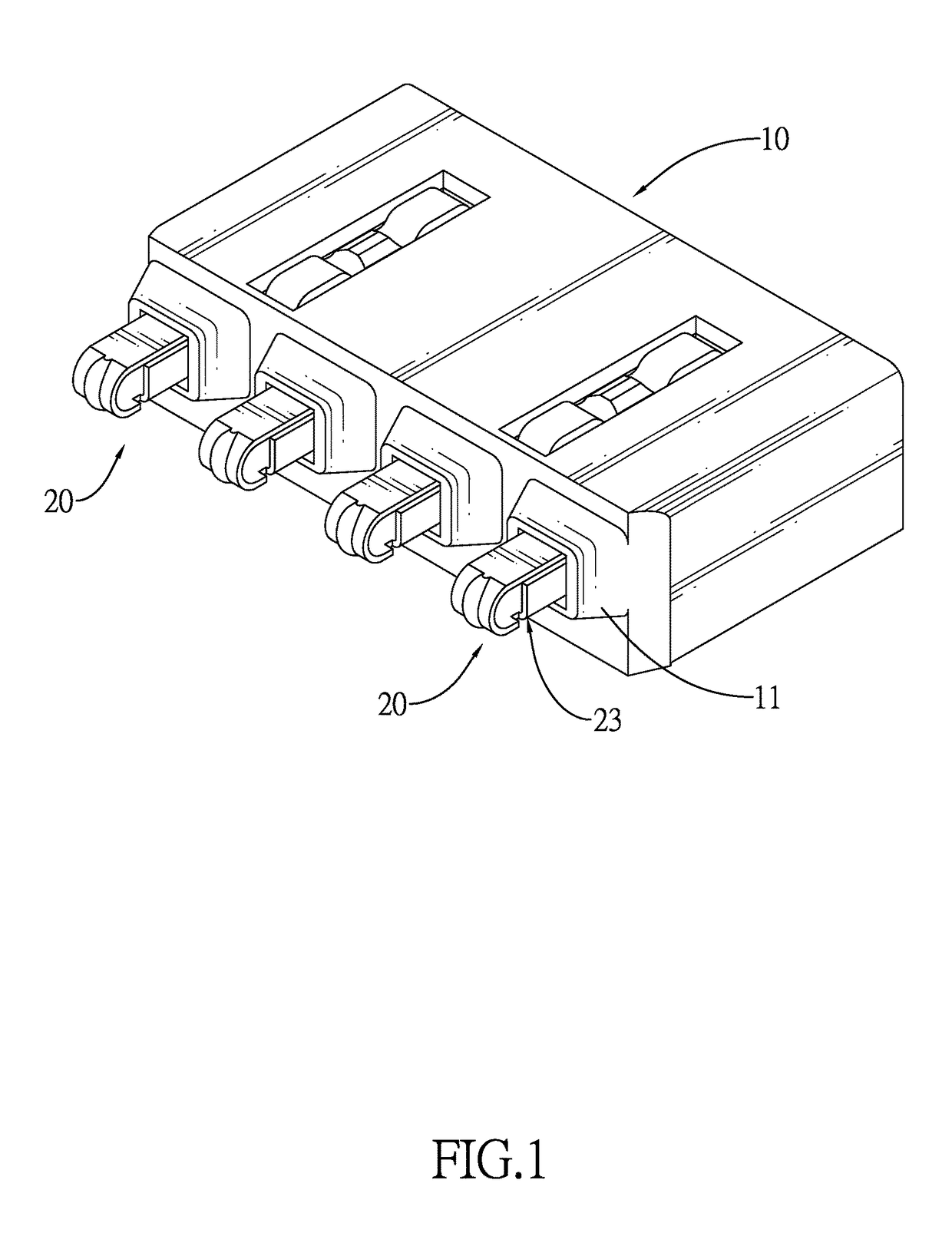
[0018]With reference to FIG. 1, an electrical connector in accordance with the present invention comprises an insulative body 10 and multiple terminals 20.

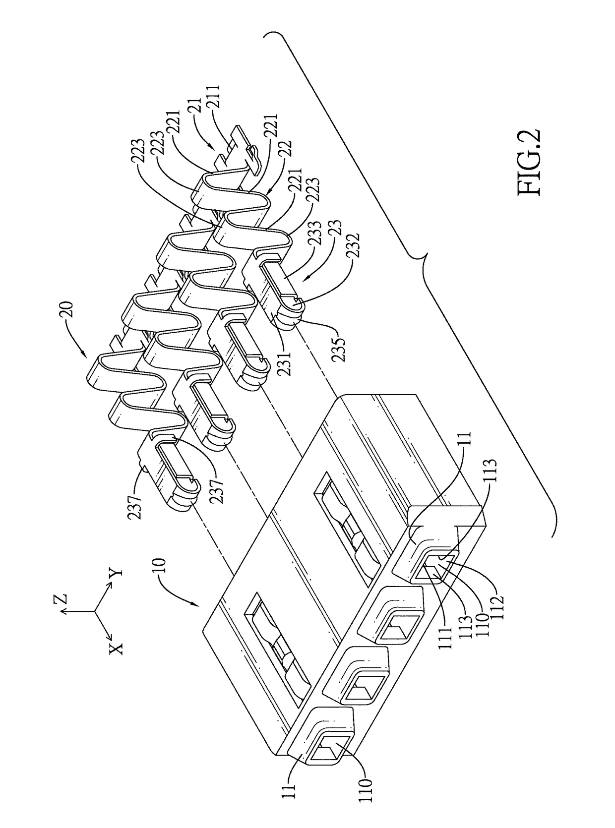
[0019]With further reference to FIGS. 2 and 3, the insulative body 10 has multiple mounting holes 100 and multiple guiding members 11. The mounting holes 100 are defined in the insulative body 10. The guiding members 11 are formed on a front end of the insulative body 10 and correspond to the mounting holes 100. Each guiding member 11 has a guiding channel 110. The guiding channel 110 is rectangular, is defined in the guiding member 11, communicates with a corresponding mounting hole 100 and has an inner surface. The inner surface may have an inner top surface 111, an inner bottom surface 112 and two opposite inner side surfaces 113 formed between the inner top surface 111 and the inner bottom surface 112. A cross-sectional area of the guiding channel 110 is smaller than a cross-sectional area of the mounting holes 100.

[0020]With ...


PUM


Abstract

An electrical connector has an insulative body and multiple terminals. The insulative body has multiple mounting holes and multiple guiding channels. The terminals are mounted respectively in the mounting holes and each terminal has an electrical contacting portion mounted slidably in one of the guiding channels. The guiding channels guide and ensure a corresponding electrical contacting portion to move linearly without being inadvertently jammed or irrecoverably deformed. Therefore, the life-span of the electrical connector is increased.

Description

BACKGROUND OF THE INVENTION[0001]1. Field of the Invention[0002]The present invention relates to a connector, and more particularly to an electrical connector that has multiple one-piece terminals. Each one-piece terminal has excellent resilience to provide stable extension and retraction functions. Furthermore, the one-piece terminal is capable of linearly extending or retracting instead of extending or retracting along a non-linearly and irregularly path, which prevents the one-piece terminal from being deformed or damaged.[0003]2. Description of Related Art[0004]Electrical connectors are commonly used electrical components in electronic devices and allow the electronic device to connect to another one to implement signal transmission or power supply between the connected electronic devices.[0005]A conventional portable electronic device such as a smart phone usually has a battery chamber and a spring-type battery connector. The spring-type battery connector, as disclosed in the T...

Claims


Application Information

Patent Timeline
Patent Type & Authority Patents(United States)
IPC IPC(8): H01R13/24H01R12/57H01R13/432
CPCH01R13/2428H01R13/2464H01R12/57H01R13/432
Inventor CHU, PING-CHUANQI, XIAO-JUANDUAN, SHU-LINCHEN, CHING-TIENWAN, WEI
Owner ADVANCED CONNECTEK INC
Why Eureka
Try Eureka