Method for filling cylindrical containers, in particular cans, and filling arrangement of a filling device and a container

a cylindrical container and container technology, applied in the field of cylindrical container filling, can solve the problems of high price/performance ratio, liquid quality change, and expensive actors to be used

Active Publication Date: 2021-01-19
LEIBINGER
View PDF30 Cites 0 Cited by
  • Summary
  • Abstract
  • Description
  • Claims
  • Application Information

AI Technical Summary

Benefits of technology

[0079]Moreover, the filling valve can comprise at an end face facing the container bottom radially extending flow channels in order to allow fluid to exit from the open filling valve that contacts the container bottom, wherein the end face is provided at the filling tube, at the separation tube or at the combined separation / filling tube, depending on which filling valve is used. Such a complete accommodation of the filling valve down to the point of contacting the bottom is advantageous for a maximum displacement / compression. For contacting, the end face of the filling valve can moreover be shaped in accordance with the contour of the container bottom. However, in connection with contacting of the container bottom, an exact control action of the relative movement must be observed in order to prevent that the container becomes deformed and thus damaged. Since the exact container geometry determines the filling volume, it is particularly important that no deformations occur at the container which lead to a container volume change. Therefore, it may be preferred that the filling valve at an end face of the filling tube, of the separation tube or of the combined separation / filling tube that is facing the container bottom has a circumferentially extending spacer or several distributed spacers that are embodied to be elastic / springy and can thus contact the container bottom without risking deformation thereof.
[0080]Particularly preferred, a circumferentially extending unilaterally acting annular seal with valve function such as a sealing lip can be employed in this context that not only acts as a springy spacer but also opens in one direction in order to allow flow of fluid out of the filling valve into the container, while sealing in opposite direction, and in this way prevents a return flow—or when the container pressure is higher than the filling pressure—also penetration of gas from the container into the region below the filling valve opening.

Problems solved by technology

In case of oxygen-sensitive liquids, it is to be prevented in this context that the liquid comes into contact with the oxygen of the ambient air and that undesirable gas binding, gas exchange or gas introduction occurs which, due to oxidation reactions or increased germ contamination, may result in a quality change of the liquid.
Disadvantage of these measuring devices is their price / performance ratio and that expensive control electronics (PLC) must be very precise, respectively, and therefore expensive actors must be used.
The reduction of ambient air oxygen in the container interior required for filling containers such as cans, the provision of the pressurization pressure required for counter pressure filling, and monitoring and maintaining the correct filling quantity lead to a complex construction of the filling device and to a failure-prone filling process.

Method used


Image

  • Method for filling cylindrical containers, in particular cans, and filling arrangement of a filling device and a container
  • Method for filling cylindrical containers, in particular cans, and filling arrangement of a filling device and a container
  • Method for filling cylindrical containers, in particular cans, and filling arrangement of a filling device and a container

Examples


Embodiment Construction

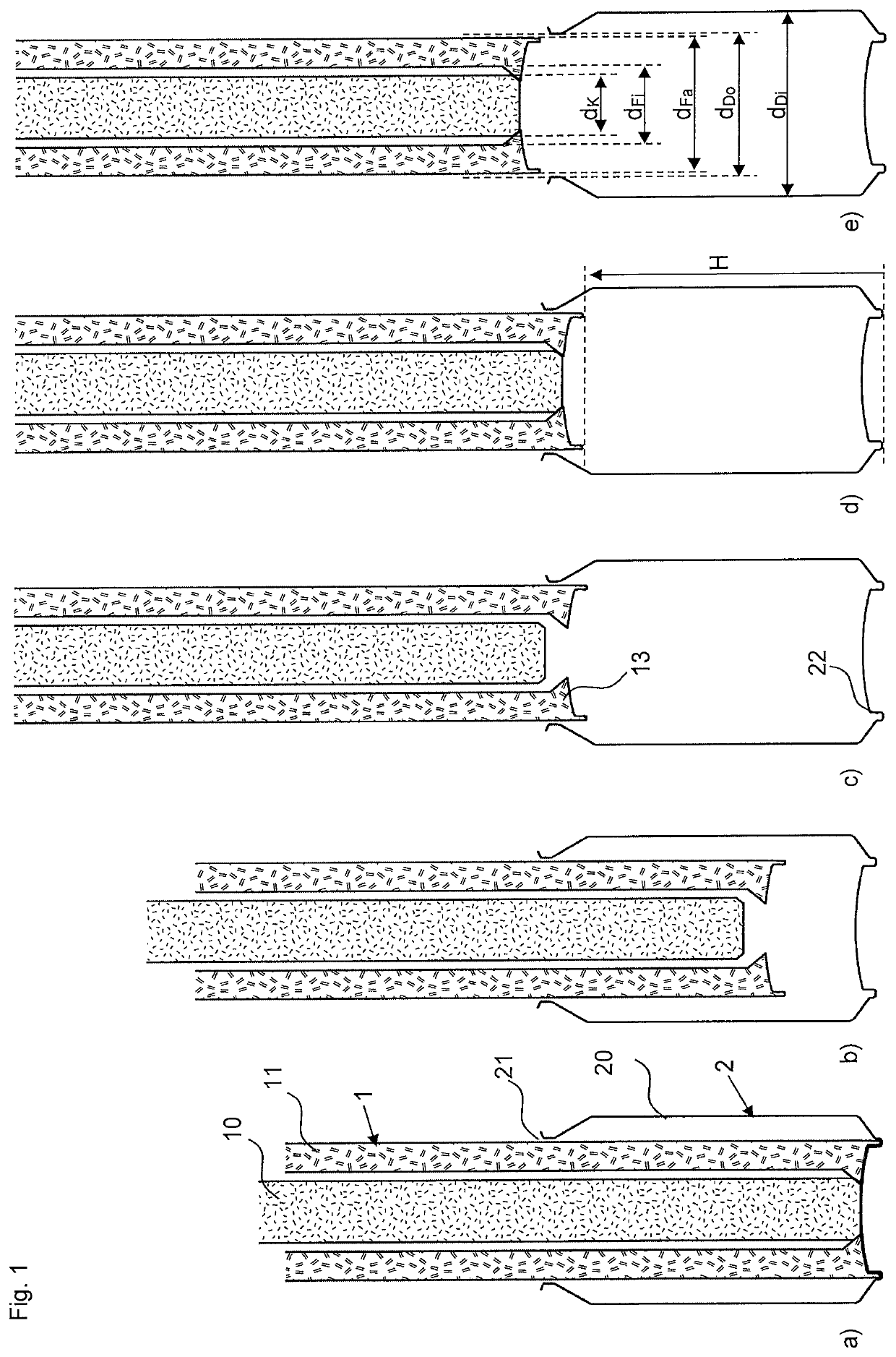
[0107]The invention concerns filling of cylindrical containers—for example, cans—by means of a special filling arrangement. In this context, advantage is taken of the fact that cans, which in addition to bottles and cartons are the most important packaging for beverages, primarily for carbon dioxide-containing beverages such as beer or soft drinks, have an extremely precisely produced cylindrical shape with a coaxial filling opening that is only minimally smaller than the container diameter. The most commonly used can volumes in Europe are 0.33 l and 0.5 l, but there are also cans with a volume of 0.15 l, 0.2 l, and 0.25 l, as well as 1 l and 5 l. According to the invention, however, also containers with other volumes can be filled as long as the container volume is known.

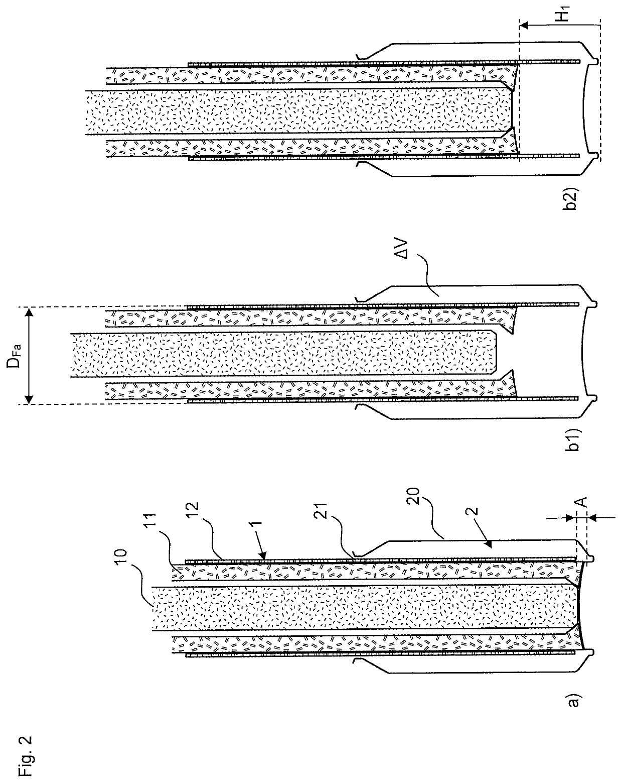
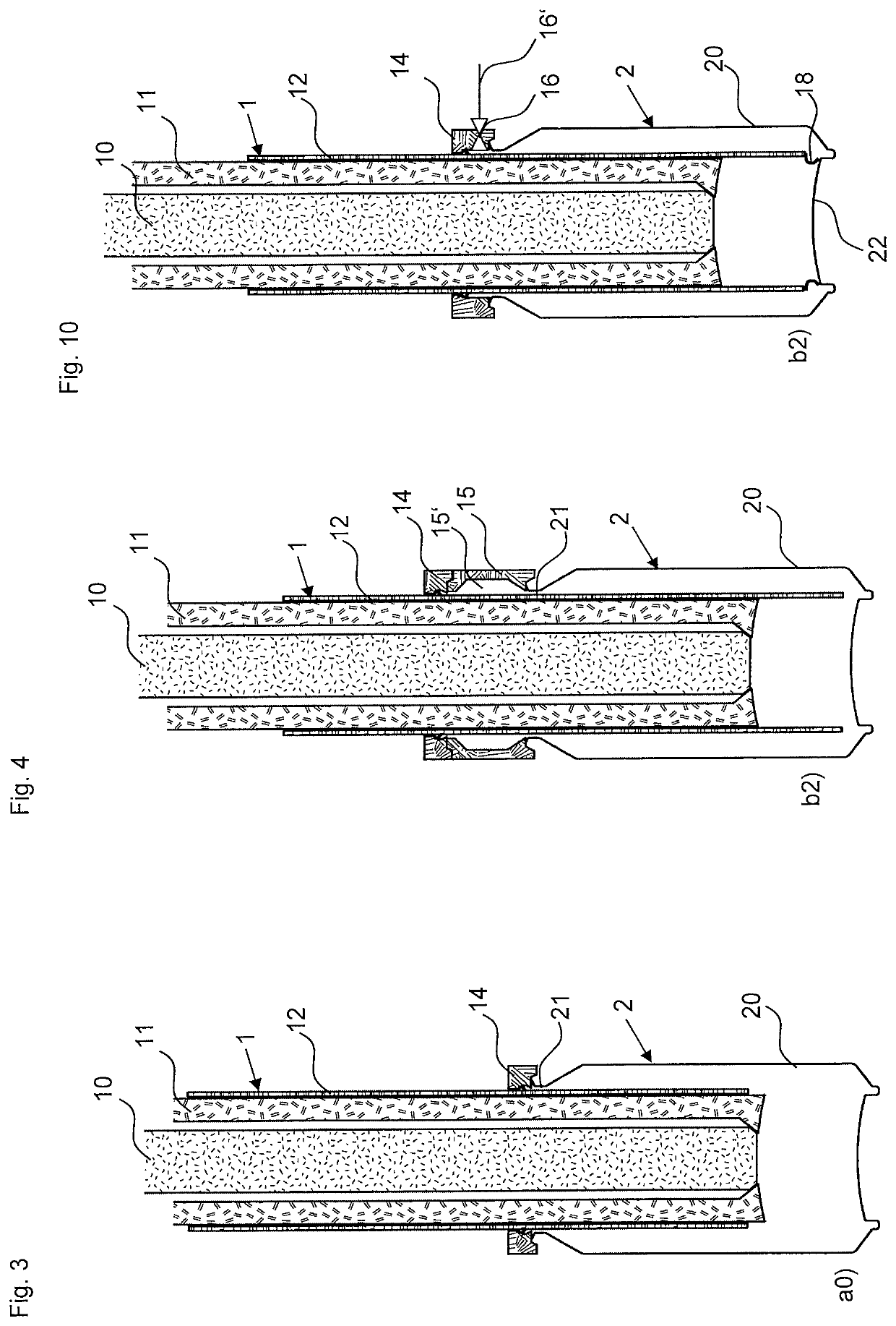
[0108]In the Figures, respective sequences of the filling arrangement in different method steps are illustrated; reference characters are therefore not provided in each illustration of the filling arrangement. The ...


PUM

PropertyMeasurementUnit
volumeaaaaaaaaaa
volumeaaaaaaaaaa
volumeaaaaaaaaaa

Abstract

In a method for filling a predefined cylindrical container, a closed filling valve is moved with its filling tip through the container opening into the container. A gas contained in the container is displaced or compressed in the container. The container opening is sealed about the filling valve; the point in time of sealing determines a pressure in the container. The container is filled by opening the filling valve to allow fluid flow. The end face of the filling valve is below a fluid level in a radial gap volume between container wall and filling valve. Upward movement of the filling valve is adjusted according to predefined control parameters; filling occurs below fluid level in that the fluid level is above the end face of the filling valve. The filing valve is closed upon reaching the predefined filling volume. The closed filling valve is removed from the container.

Description

BACKGROUND OF THE INVENTION[0001]The invention concerns a method for filling cylindrical containers, in particular cans, with fluid, as well as filling arrangements of filling device and a predefined cylindrical container that are suitable for performing the method.[0002]Filling devices and methods for filling containers are known in various embodiments. In case of oxygen-sensitive liquids, it is to be prevented in this context that the liquid comes into contact with the oxygen of the ambient air and that undesirable gas binding, gas exchange or gas introduction occurs which, due to oxidation reactions or increased germ contamination, may result in a quality change of the liquid. Therefore, containers that are to be filled with such a liquid are, for example, evacuated prior to the actual filling process and / or the container interior is purged with an inert gas etc., for which purpose usually corresponding controllable feeding and discharging gas passages are formed in the respectiv...

Claims


Application Information

Patent Timeline
Patent Type & Authority Patents(United States)
IPC IPC(8): B67C3/26B65B3/06B65B3/18B65B3/26
CPCB67C3/26B65B3/06B65B3/18B65B3/26B67C2003/268B67C2003/2657B67C2003/2671
Inventor LEIBINGER, BENEDIKT
Owner LEIBINGER
Why Eureka
Try Eureka