Tray and heat treatment method

a technology of heat treatment and trays, which is applied in the field of trays and heat treatment methods, can solve the problems of decreasing efficiency and decreasing the use efficiency of the factory space, and achieve the effects of reducing the space for storing the trays, reducing the use efficiency of the factory space, and reducing the setup change tim

Active Publication Date: 2019-07-30
MITSUI HIGH TEC INC
View PDF29 Cites 0 Cited by
  • Summary
  • Abstract
  • Description
  • Claims
  • Application Information

AI Technical Summary

Benefits of technology

[0012]Such a tray (conveyance jig) includes a positional displacement regulating part so as to prevent the workpieces from being unequally heat-treated or being damaged due to contact between the mutual workpieces in a process of heat treatment or a process of conveyance, and regulates a horizontal positional displacement of the workpiece with respect to the tray. The positional displacement regulating part is, for example, a recess or a protrusion formed according to a plane shape of the workpiece.
[0014]The present invention has been implemented in view of such circumstances, and a non-limited object of the present invention is to provide a tray capable of conveying plural kinds of workpieces with different dimensions or shapes in the tray for carrying the placed workpieces in and out of a heat treatment furnace. Also, another non-limited object of the present invention is to provide a heat treatment method capable of preventing the workpieces from being deformed or being damaged in a heat treatment process or during conveyance of the plural kinds of workpieces with the different dimensions or shapes.
[0025]Since the tray according the aspect of the present invention includes the plural kinds of positional displacement regulating parts for respectively regulating the horizontal positional displacements of the plural kinds of workpieces with the different sizes in the tray, the plural kinds of workpieces with the different sizes can be conveyed by the single tray. As a result, it becomes unnecessary to prepare the dedicated tray every type of workpiece. Consequently, space for storing the tray can be decreased. As a result, use efficiency of the space in a factory is increased. Also, since it becomes unnecessary to replace the tray every time the workpiece is changed, setup change time is shortened and productivity is increased.
[0026]Also, since the heat treatment method according to the aspect of the present invention can prevent the workpieces from being deformed or being damaged in a heat treatment process or during conveyance of the plural kinds of workpieces with the different sizes, quality of a product is improved.

Problems solved by technology

As a result, in a heat treatment line in which many types are mixed and processed, it is necessary to prepare space for storing many kinds of trays inside a factory, with the result that there is a problem of decreasing use efficiency of the space of the factory.
Also, since the tray placed on the line is changed every time the type targeted for processing is changed, setup change time is required, with the result that there is a problem of decreasing efficiency.

Method used


Image

  • Tray and heat treatment method
  • Tray and heat treatment method
  • Tray and heat treatment method

Examples


Embodiment Construction

[0040]A tray and a heat treatment method according to an embodiment of the present invention will hereinafter be described in detail with reference to the accompanying drawings.

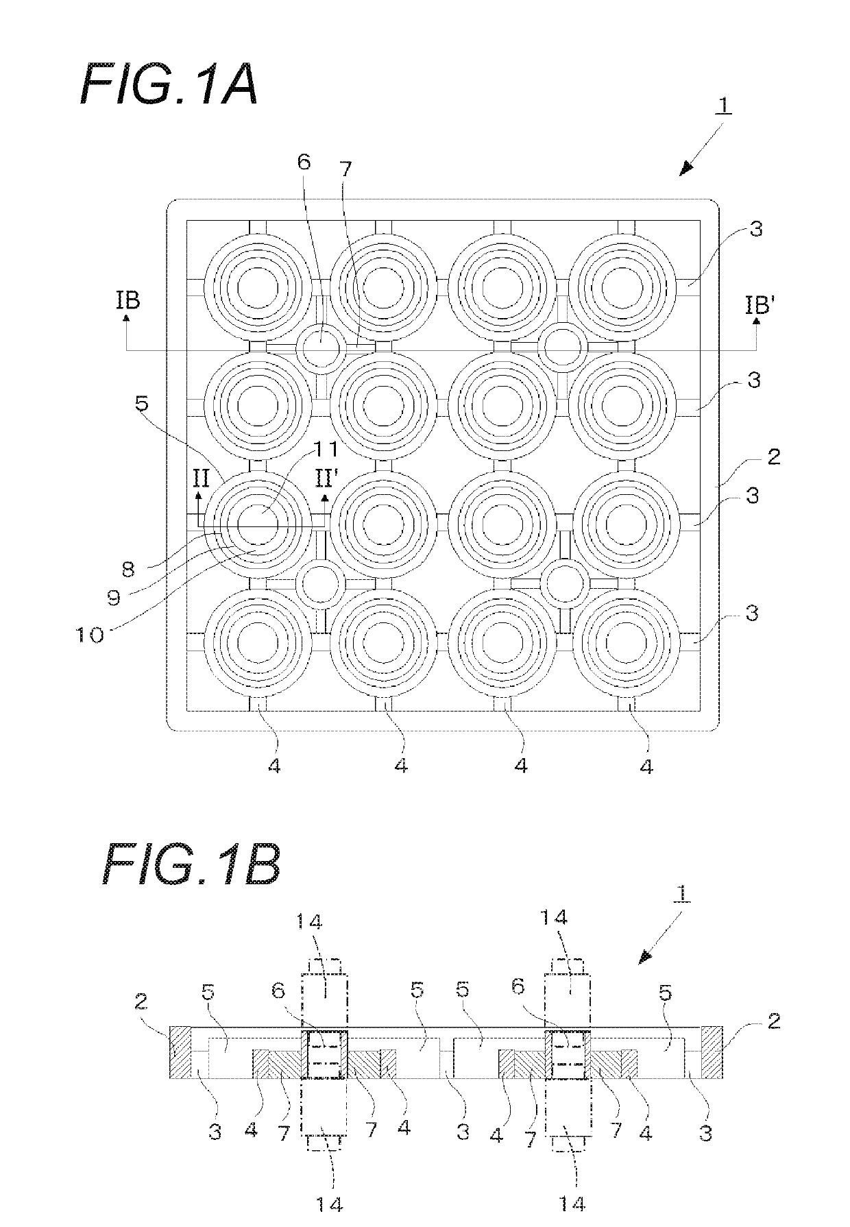
[0041]FIGS. 1A and 1B are explanatory diagrams showing a configuration of a tray 1 according to the embodiment of the present invention. As shown in FIG. 1A, the tray 1 includes an, outer frame 2 with a rectangular shape in plan view. Four transverse beams 3 and four longitudinal beams 4 are respectively arranged in a grid shape inside the outer frame 2. Both ends of the transverse beams 3 and the longitudinal beams 4 are coupled to the outer frame 2, and a total of sixteen placement parts 5 are fixed to points of intersections between the transverse beams 3 and the longitudinal beams 4. That is, the placement parts 5 are coupled to the outer frame 2 through the transverse beams 3 and the longitudinal beams 4. In addition, a function and a detailed configuration of the placement part 5 will be described below...


PUM

PropertyMeasurementUnit
sizesaaaaaaaaaa
positional displacementaaaaaaaaaa
sizeaaaaaaaaaa

Abstract

A tray is provided for conveying a workpiece placed on the tray inside a heat treatment furnace. The tray includes plural kinds of positional displacement regulating parts for respectively regulating horizontal positional displacements of plural kinds of workpieces with different sizes, wherein the plural kinds of positional displacement regulating parts are arranged concentrically in a plane shape.

Description

CROSS REFERENCE TO RELATED APPLICATION[0001]This application is based upon and claims the benefit of priority of Japanese Patent Application No. 2016-035915 filed on Feb. 26, 2016, the contents of which are incorporated herein by reference in its entirety.BACKGROUND OF THE INVENTION[0002]1. Field of the Invention[0003]The present invention relates to a tray carried in and out of a heat treatment furnace together with a workpiece placed on the tray, and a heat treatment method using the tray.[0004]2. Description of the Related Art[0005]Heat treatment is a generic term of treatment in which properties of a workpiece are changed by heating or cooling. The heat treatment includes quenching, tempering, annealing, normalizing, oil quenching, blackening treatment, etc. (see JP-A-2003-113421 as Patent Literature 1). In a manufacturing step of a laminated iron core such as an armature iron core of an electric motor or a generator, various items of heat treatment are conducted. For example, t...

Claims


Application Information

Patent Timeline
Patent Type & Authority Patents(United States)
IPC IPC(8): F27D3/12F27D5/00
CPCF27D3/12F27D5/00F27D2005/0081F27D2003/124C21D9/0025
Inventor KOZONO, TAKEAKIHASUO, YUSUKE
Owner MITSUI HIGH TEC INC
Why Eureka
Try Eureka